


48
Setup Software (continued)
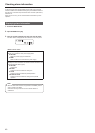
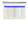
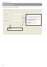
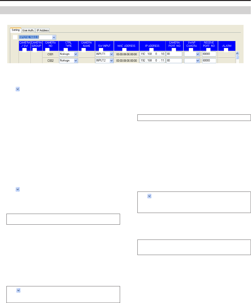
Displaying the “Setting” tab
1
2 3 4 5 6 7 8 9 10 11 12 13
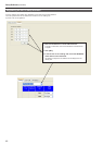
1 Setting target selection list box
Select the unit for which to configure the connection settings.
Click
to display the IP addresses of the units that can be set from
this software. Select the IP address of the unit you want to set from
this list.
Any of the units registered in the “IP Address” tab can be selected.
⇒ “Registering the unit in Setup Software” (page 46)
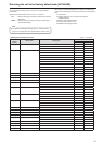
2 CAMERA/SW
Displays the types of devices to be connected.
CAMERA : Remote camera
SW : Switcher
3 CAMERA GROUP
Displays the camera group numbers.
4 CAMERA NO.
Displays the camera numbers.
5 CTRL TYPE
Select the connection types.
Click
on the right and select a connection type from “Serial”,
“Network”, or “NoAsign”.
Serial : Serial connection
Network : IP connection
NoAsign : No setting (default setting)
“Serial” can only be selected with GROUP1.
After making a change, click the [SET] button to reflect the change.
6 CAMERA NAME
Displays the names of the cameras set on the remote cameras.
They are displayed for the remote cameras in the currently selected
group.
For remote cameras with a serial connection, a name is only
displayed when a
remote camera is selected on the unit.
7 SW INPUT
Set the image inputs of the switcher that correspond to the camera
numbers on the unit.
Click on the right and select an option from “NoAsign” and “INPUT1”
to “INPUT100".
After making a change, click the [SET] button to reflect the change.
8 MAC ADDRESS
Displays the MAC addresses of the remote cameras and switcher
linked to the camera numbers on the unit.
9 IP ADDRESS
Set the IP addresses of the remote cameras and switcher that are
connection destinations.
After input, click the [SET] button to reflect the changes.
10 CAMERA PORT NO
Set the port numbers of the remote cameras that are connection
destinations.
After input, click the [SET] button to reflect the changes.
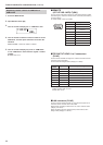
Possible setting range: 1 to 65535
However, the following values cannot be set even though they are
within this range.
20, 21, 23, 25, 42, 53, 67, 68, 69, 110, 123, 161, 162, 995, 10669,
10670
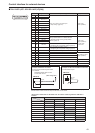
11 SWAP CAMERA
Swap the remote cameras set as connection destinations between
two camera numbers.
Click to display camera numbers “C001” to “C100”.
Select the camera number with which you want to make the swap from
this list.
After making a change, click the [SET] button to reflect the change.
12 RECEIVE PORT NO
Set the port numbers for the unit to receive camera information
update notifications from remote cameras.
Possible setting range: 61000 to 65534
Only an even number can be set.
Even if an odd number is entered and then the [SET] button is clicked,
the value is not reflected.
13 ALARM
Displays the alarm information of the remote cameras.
It is displayed for the remote cameras belonging to the camera
group selected on the unit.
For remote cameras with a serial connection, the information is only
displayed when a remote camera is selected on the unit.