


3-11
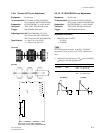
DXC-D35/D35WS(UC)
DXC-D35P/D35WSP(CE) V1
B
A
B
A
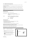
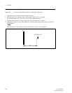
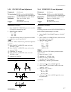
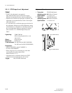
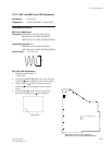
3-3-10. VF SYNC/BLKG Level Adjustment
Equipment: Oscilloscope
To be extended: ES-32 board (for DXC-D35/D35P)
ES-33 board
(for DXC-D35WS/D35WSP)
Preparation: OUTPUT/DL/DCC + switch: BARS
Test point: TP82 (GND: TP83)/EX-490 board
Trigger: HD (TP84/EX-490 board)
Adjustment Procedure
1. SERVICE menu “PAGE 7”
VF SYNC
→ VF BLKG
n
For the adjustment procedure, at the first “VF BLKG”
adjustment is done, and next, “VF SYNC” adjustment is
done.
2. Adjust the following items by UP switch or DOWN
switch to meet the specification.
Item Test Point Specification
VF BLKG TP82 NTSC: A = 50 ±10 mV
PAL: A = 50 ±10 mV
VF SYNC TP82 NTSC: B = 290 ±10 mV
PAL: B = 300 ±10 mV
[for NTSC] [for PAL]
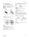
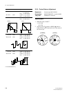
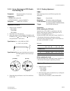
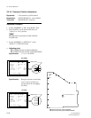
3-3-9. Chroma (YC) Level Adjustment
Equipment: Oscilloscope
To be extended: ES-32 board (for DXC-D35/D35P)
ES-33 board
(for DXC-D35WS/D35WSP)
Preparation: OUTPUT/DL/DCC + switch: BARS
Test point: TP64 (GND: TP65)/EX-490 board
Trigger: HD (TP84/EX-490 board)
Adjusting point: 1RV505 (CHROMA (YC) LEV)
/ES-32 board (for DXC-D35/D35P)
/ES-33 board
(for DXC-D35WS/D35WSP)
Specification: A = 286 ±5 mV (for NTSC)
A = 300 ±10 mV (for PAL)
[for NTSC]
[for PAL]
3-3. Camera Adjustment
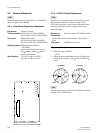
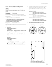
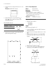
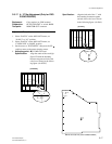
TP501
RV501
RV502
RV503
RV504
RV505
E501
FL502
CN501
1
2
3
4
5
6
A
B C
D
ES-32 board (A side) (DXC-D35/D35P)
ES-33 board (A side) (DXC-D35WS/D35WSP)