


1-28
DXC-D35/D35WS(UC)
DXC-D35P/D35WSP(CE) V1
54
Chapter 4 Viewfinder Screen Indications and Menus
Chapter 4 Viewfinder Screen Indications and Menus
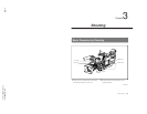
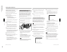
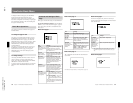
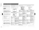
Viewfinder Normal Indications
During normal operation, the following items can be
indicated in the viewfinder.
The significance of each of the indications shown in
the figure is as follows.
1 VTR operation status indication
This indicates the VTR’s current operation status
(REC, PLAY, etc.).
2 TAKE/CUE indication
This displays a TAKE or CUE indicator when using
the ClipLink function and recording with the DSR-1/
1P.
TAKE: When recording in Mark mode, this
indication appears when a Mark IN point is set
and disappears when the next Mark OUT point is
set.
CUE: When recording in Cue mode, this indication
appears for about 1 second when a cue point is set.
3 Recording time or time data indication
This shows the following values.
•When the REC TIME switch on the camera is in the
TTL position: The total recording time
•When the REC TIME switch on the camera is in the
DUR position: The duration of the current recording
cut
•With a VTR connected, when the REC TIME switch
on the camera head is in the OFF position and the
item TC IND in advanced menu page 6 is set to
“ON”: A time data value from the VTR depending on
the DISPLAY switch settings on the VTR as shown
in the following table
When using the DSR-1/1P, time data values appear
during playback, fast forward, rewind, or recording
review.
4 NG indication
An “NG” (No Good) indicator appears if you
designate a recorded scene as “NG” when using the
ClipLink function and recording with the DSR-1/1P.
REC TAPE NEAR END
TAKE
TCG 12:34:56:00
W:A
NG AUTO BLACK
SKIN
CLIPM
-OK-
EVS
198
F5.6
DRP 18dB
EZ FOCUS
56ND
:LOW LIGHT 99 04 01
SS :1/100 10:00
AM
30-25 BATT:14.4V
a) Displayed only when a DSR-1/1P is connected.
b) Displayed only when a PVV-3/3P is connected.
c) Whether or not to display can be selected by menu setting.
d) This is recorded over the picture being shot.
qd VTR warning indication
a), b)
qh EVS indication
qj Lens f-stop indication
c)
qk Gain indication
c)
ql Filter setting indication
c)
w; Clock indication
a), b), c), d)
wa Voltage/error indication
ws Shutter setting indication
c)
qf White balance indication
c)
qg SK/N DTL indication
c)
1 VTR operation status indication
a), b)
2 TAKE/CUE indication
a)
3 Recording time or time data
indication
a), b), c)
4 NG indication
a)
5 Clip mode indication
a)
6 Clip remaining
indication
a)
7 Status display area
8 EZ FOCUS indication
9 LOW LIGHT indication
c)
0 Camera microphone output
indication
c)
qa Audio recording level indicators
a), b), c)
qs Tape remaining indication
a), b), c)
DISPLAY switch
setting
Time data displayed
COUNTER CNT: Tape transport time
TC TCG: a time code from the time code
generator
TCR: a time code from the time code
reader
UBG: a user bit value from the user
bit generator
U-BIT
Chapter 4 Viewfinder Screen Indications and Menus
55
Chapter 4 Viewfinder Screen Indications and Menus
5 Clip mode indication
A “CLIP M” or “CLIP C” indication appears when
you use the ClipLink function and record using the
DSR-1/1P.
CLIP M: Indicates shooting in Mark mode
CLIP C: Indicates shooting in Cue mode
6 Clip remaining indication
The number of available index pictures remaining is
displayed when you use the ClipLink function with the
DSR-1/1P.
7 Status display area
One of the following values or messages is displayed
to indicate the camera head’s current status or its
operation status.
•New values when changing camera head’s settings
•Messages indicating progress or results of
adjustments
•The camera head’s current settings
•SetupLog data recorded to tape during shooting (see
page 78)
Note
The status indication is not shown while the EZ
FOCUS indication 8 appears.
8 EZ FOCUS indication
This appears when the EZ FOCUS button is pressed,
enabling the “easy focus” function.
9 LOW LIGHT indication
This warning appears if the lighting level is
inadequate.
0 Camera microphone output indication
This appears when there is an input from the camera
microphone.
Note
This indication serves as a check on whether the
camera microphone is operating correctly, but it does
not provide confirmation that the VTR is recording
sound. Check that the audio recording levels on the
VTR are set correctly.
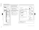
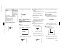
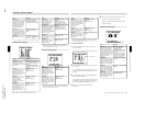
qa Audio recording level indicators
These show the recording levels of audio channels 1
and 2 on the VTR.
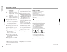
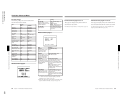
qs Tape remaining indication
This shows the tape remaining in the VTR as follows.
qd VTR warning indication
This shows warning indications about operation or
status of the connected VTR.
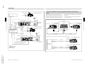
When connecting the DSR-1/1P or PVV-3/3P
Channel 1
Channel 2
–20 dB
–
∞
+3 dB
0 dB
0 dB
–2 dB
PVV-3/3P
DSR-1/1P
Indication Tape remaining
F-30 At least 30 minutes
30-25 25 - 30 minutes
25-20 20 - 25 minutes
20-15 15 - 20 minutes
15-10 10 - 15 minutes
10-5 5 - 10 minutes
5-0 2 - 5 minutes
5-0 (flashing) 0 - 2 minutes
Indication
Meaning
NO TAPE There is no tape loaded.
REC INHIBIT
The tape is in the recording inhibited
state.
LOW BATT.
The battery is almost exhausted.
BATT. END
The battery is exhausted.
TAPE NEAR END The tape is near the end.
TAPE END The tape is at the end.
CHECK REMOTE
(PVV-3/3P only)
A device other than a remote control
unit (e.g. headphones) is connected to
the REMOTE connector.
SERVO The servo lock has been lost.
HUMID
SLACK
OXIDE TAPE
(PVV-3/3P only)
An oxide tape has been loaded. (The
tape is automatically ejected.)
There is condensation.
The video heads are clogged, or there
is some other fault in the recording
system.
The tape is not wound properly.
RF