


1-29
DXC-D35/D35WS(UC)
DXC-D35P/D35WSP(CE) V1
56
Chapter 4 Viewfinder Screen Indications and Menus
Chapter 4 Viewfinder Screen Indications and Menus
Only when connecting the DSR-1/1P
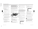
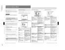
qf White balance indication
The following indications appear.
qg SKIN DTL indication
This appears when the skin detail function is activated
(The SKIN DTL switch is set ON.)
qh EVS indication
This appears when the EVS (Enhanced Vertical
definition System) function is enabled. (See page 84.)
qj Lens f-stop indication
This shows the f-stop of the lens.
Note
Depending on the lens being used, this indication may
differ slightly from the actual f-stop on the lens.
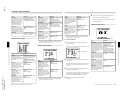
qk Gain indication
This shows the gain value, and the settings of the
HYPER GAIN switch and the DPR (Dual Pixel
Readout) function (see page 64) as shown in the
following table.
ql Filter setting indication
This shows the setting of the FILTER control.
w; Clock indication
The clock indication is shown in one of the following
ways (according to the CLOCK IND setting of CAM,
BARS, or OFF in advanced menu page 8).
CAM: Always displayed.
BARS: Displayed whenever color bars are
displayed.
OFF: Not displayed.
If the clock indication is displayed during recording, it
is recorded onto the image.
Indication
Meaning
50P CONNECT Connection with the PRO 50-pin
connector on the DSR-1/1P.
(Freeze mix function is disabled.)
MP TAPE An incorrect type of cassette has
been loaded. (The cassette is
automatically ejected and the
indication disappears in about two
seconds.)
CLIP DATA ERR Abnormality of the cassette memory
data.
AUDIO 48kHz?
(4 flashes/s)
At back space editing, audio
recording mode has changed from
32 kHz mode (4-channel mode) to
48 kHz mode (2-channel mode).
AUDIO 32kHz?
(4 flashes/s)
At back space editing, audio
recording mode has changed from
48 kHz mode (2-channel mode) to
32 kHz mode (4-channel mode).
ERROR:91-13F Failure in loading or saving the
cassette memory data.
When other error indication
appears, refer to the operating
instructions for the DSR-1/1P.
CLIP CONT?
Asking whether you will continue
shooting in ClipLink mode or not
when the cassette contains ClipLink
data. (The indication disappears
when you press the ClipLink
CONTINUE button on the DSR-1/
1P or start the next shooting without
pressing it.)
CLIP NEAR END
CLIP END Impossible to record any more clip
shots.
At back space editing in ClipLink
mode, capacity for only 1 to 3 index
pictures remains.
Indication Meaning
EZ Operating in EZ mode (The ATW function is
selected.)
ATW The ATW function is selected. (The ATW
button was pressed and the indicator is lit.)
W:A White balance memory A is selected.
W:B White balance memory B is selected.
W:P Preset white balance is selected.
W:M Manual adjustment is performed remotely.
Example indication Meaning
18dB Gain setting is 18 dB.
DPR 18dB The DPR function is enabled.
In this case the DPR function
approximately doubles the gain (an
increase of 6 dB) over the current
gain setting (in this case 18 dB).
HYPER The HYPER GAIN switch is in the
ON position.
In this case the hyper gain function
increases the gain by a factor of
about 60 or 120 with respect to 0
dB regardless of the current gain
setting (that is, increased to 36 or
42 dB).
Indication Filter setting
3200 1 (3200K)
56ND 2 (5600K +
1
/
8
ND)
5600 3 (5600K)
56ND 4 (5600K +
1
/
64
ND)
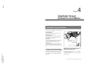
Viewfinder Normal Indications
Chapter 4 Viewfinder Screen Indications and Menus
57
Chapter 4 Viewfinder Screen Indications and Menus
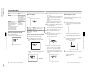
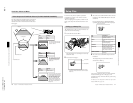
wa Voltage/error indication
The current voltage is displayed whenever the camera
head’s power supply voltage dips below 11.0 V DC.
However, you can also display the current voltage at
any time by pressing and holding the MENU/STATUS
switch in the upward position (the display is shown for
as long as you hold the switch upward).
An error message is displayed when an abnormality
has been detected by the auto diagnostic function
(page 62).
If an error message appears, contact your Sony dealer.
If using a VTR and an Anton Bauer Intelligent
Battery System
The remaining battery capacity is shown as a
percentage.
ws Shutter setting indication
When the SHUTTER switch has been set to ON, the
shutter speed, CLS frequency or EVS set in basic
menu page 1 is displayed here.
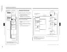
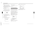
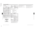
Status Indications
If you set the MENU/STATUS switch to STATUS
while a menu is being displayed, the camera head’s
current setting status will be shown in this display
area.
a) When both the DCC+ and DynaLatitude
functions are set to OFF
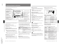
Display
Description
WHITE White balance adjustment method
selection (PRE/A/B) and color
temperature during auto white
balance adjustment
A.IRIS
FILE STD (when not using the setup files),
or a selected file name (when using
the setup files) (see page 71).
Iris adjustment method selection
(STD/SPOT L/BACK L)
For DCC+ indication: ON with the
OUTPUT/DL/DCC+ switch set to
CAM/DCC+ (DCC+ON), and OFF with
the switch set to CAM/DL and DL in
advanced menu page 2 (page 64) set
to OFF (both DCC+ and DynaLatitude
OFF).
For DL indication: When setting the
OUTPUT/DL/DCC+ switch to DL and
DL in advanced menu page 2 to OFF
(DynaLatitude OFF), LOW, STD or
HIGH is displayed according to DL
LEV setting in basic menu page 2
(page 59).
DCC+ or DL