


2-15
DXC-D35/D35WS(UC)
DXC-D35P/D35WSP(CE) V1
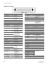
Shoe
Screws
K3 x 6
Screws
K3 x 6
Screws
K3 x 6
Stop screw
Blind
plate
Plate
spring
VF connection cable
(20pin)
Fixing ring
Stop screw
Shoe
Guide plate
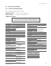
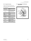
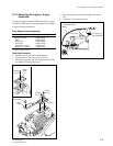
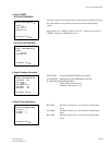
2-10. Attaching the 4-type or 5-type
Viewfinder
An optional 4-type viewfinder (DXF-40 series) or 5-type
viewfinder (DXF-50 series) can be attached in accordance
with the following procedures:
Parts Required (sold separately)
Name Sony Part No.
. Accessory shoe kit A-8274-968-B
Shoe 3-664-218-0X
Plate spring 3-664-228-0X
Stop screw 3-664-213-0X
Screw K3 x 6 (4 pcs) 7-682-247-0X
Screw K3 x 12 (4pcs)
*1
7-682-250-0X
*1 : These screws are not used.
Attaching Procedure
1. Remove a screw and remove the blind pate.
2. Tighten the shoe with four screws (K3 x 6).
3. Fix the plate spring in the shoe in the arrow direction
and tighten it with the stop screw.
4. Fit the guide plate in the shoe and tighten the fixing
ring.
5. Connect the VF connection cable.
2-10. Attaching the 4-type or 5-type Viewfinder