


1-34
DXC-D35/D35WS(UC)
DXC-D35P/D35WSP(CE) V1
66
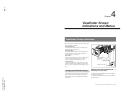
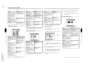
Chapter 4 Viewfinder Screen Indications and Menus
Chapter 4 Viewfinder Screen Indications and Menus
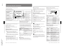
Item
Settings
×1: Uses only the upper
REC/TALLY indicator.
×2 (normal value): Uses
two REC/TALLY indicators.
VF TALLY
Selects whether or not to use
more than one REC/TALLY
indicators in the viewfinder
(displayed only when the
DXF-701/701CE/701WS/
701WSCE/801/801CE
viewfinder is attached).
VF PLAY
Selects the video signal
displayed in the viewfinder
during playback of the DSR-
1/1P (displayed only when
the DSR-1/1P is connected)
Y (normal value): Y signal
VBS: Composite video
signal
LENS SEL
Selects the types of the lens.
1 (normal value), 2, 3, 4
For details, see “Designating
the lens” on page 90.
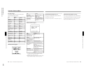
Advanced menu page 5
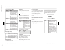
Item
Settings
SS IND
a)
Selects the mode for
showing the shutter setting
when displaying the normal
indications.
3SEC: Displays shutter
setting for three seconds only
when the setting has been
changed.
ALWAYS (normal value):
Displays the shutter setting at
all times.
LL IND
a)
Selects whether or not to
show the LOW LIGHT
indication on the normal
indications when inadequate
lighting is detected.
ON (normal value):
Displays.
OFF: Not display.
MIC IND
a)
Selects whether or not to
show the camera
microphone output
indication on the normal
indications.
ON (normal value):
Displays.
OFF: Not display.
IRIS IND
a)
Selects whether or not to
show the lens’s F-stop value
(iris indication) on the
normal indications. The F-
stop value is always
displayed when in EZ mode.
ON (normal value):
Displays.
OFF: Not display.
a) When the viewfinder’s DISPLAY switch is set to OFF,
indications related to these items are not displayed even
when menu settings are set to ON.
GAIN IND
a)
Selects whether or not to
always show the gain
setting indication on the
normal indications.
ON (normal value): Always
displays.
OFF: displays for two
seconds only when the
setting has been changed.
FILTER IND
a)
Selects whether or not to
always show the FILTER
knob setting indication on
the normal indications.
The FILTER knob setting
indicator is always displayed
when in EZ mode.
ON (normal value): Always
displays.
OFF: Displays for two
seconds only when the
setting has been changed.
Item
Settings
WHITE IND
a)
Selects whether or not to
show the setting of the white
balance switch.
ON (normal value): Displays.
OFF: Not display.
SKIN IND
a)
Selects whether or not to
show the setting for skin
detail correction.
ON (normal value): Displays.
OFF: Not display.
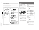
Advanced menu page 6
a) When the viewfinder’s DISPLAY switch is set to OFF,
indications related to these items are not displayed even
when menu settings are set to ON.
Item Settings
AUDIO IND
a)
Selects whether or not to
show the audio level
indication on the normal
indications (valid only when
the DSR-1/1P or PVV-3/3P
is connected).
ON (normal value):
Displays.
OFF: Not display.
TAPE IND
a)
Selects whether or not to
show the VTR’s remaining
tape indication on the normal
indications. (valid only when
the DSR-1/1P or PVV-3/3P
is connected).
ON (normal value):
Displays.
OFF: Not display.
Viewfinder Advanced Menu
Chapter 4 Viewfinder Screen Indications and Menus
67
Chapter 4 Viewfinder Screen Indications and Menus
a) When the viewfinder’s DISPLAY switch is set to OFF,
indications related to these items are not displayed even
when menu settings are set to ON.
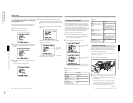
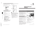
To set the camera ID
1
Press the MENU/STATUS switch to move the
cursor to ID SET.
The cursor (→) changes to the text entry arrow (↓).
2
Press the MENU/STATUS switch to move the text
entry arrow.
Press the MENU/STATUS switch upward to move
the cursor to the right or downward to move it to
the left.
3
Press the UP/ON button or DOWN/OFF button to
enter the desired characters.
The displayed character changes each time the UP/
ON button is pressed. It changes in reverse order
each time the DOWN/OFF button is pressed.
4
Return to step 2 and repeat the text entry
procedure.
TC IND
a)
Selects whether or not to
show the time data indication
on the normal indications
(valid only when the DSR-1/
1P or PVV-3/3P is
connected).
ON (normal value):
Displays.
OFF: Not display.
ID IND
Selects whether or not to
display the camera ID when
displaying color bars.
ON (normal value):
Displays.
OFF: Not display.
ID SET
Sets the camera ID (up to
eight characters, including
alphanumerics, symbols,
and spaces).
See “To set the camera ID”
below.
Item Settings
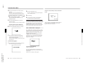
Current camera ID
5
When you have finished entering the text, move
the cursor to the parenthesis position.
This clears the displayed menu and returns to the
normal indications.
Advanced menu page 7
a) At shipping, the EZ MODE is set to STD.
Item
Settings
EZ MODE
When the EZ MODE button
has been set to EZ mode
ON, this selects whether or
not to change the settings of
other switches and menus to
the standard settings. (The
EZ mode function cannot be
used during remote
operation.)
STD (normal value):
Changes settings to
standard settings.
CUSTOM: Changes only
some settings to standard
settings.
For details of the settings
when STD or CUSTOM is
specified, see “EZ mode
settings” on next page.
A.IRIS-AGC
Selects auto iris adjustment
which sets an F-stop value
that can be switched to AGC
(displayed only when the EZ
MODE is set to CUSTOM).
F1.8, F 2.8 (normal value),
F4, F5.6
A.IRIS-AE
Selects auto iris adjustment
which sets an F-stop value
that can be switched to AE
(displayed only when the EZ
MODE is set to CUSTOM).
F5.6 , F8, F11, F16 (normal
value)
0 dB, 3 dB, 6 dB, 9 dB, 12
dB (normal value)
AGC LIMIT
Sets an upper limit value for
AGC adjustment (displayed
only when the EZ MODE is
set to CUSTOM).