


2-4
DXC-D35/D35WS(UC)
DXC-D35P/D35WSP(CE) V1
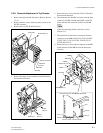
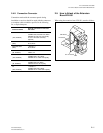
Screw (K3 x 6)
Screw
(K3 x 6)
Rear plate
Front unit assembly
Screw
(B3 x 10)
Screw
(B3 x 10)
m
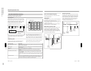
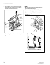
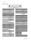
. Be sure to route the harnesses as shown in the figure
when reattaching the MB board.
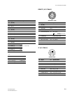
. When reinstalling the VA, PR, IF and ES boards, use
care to insert securely the connectors on each board to
the connectors of the MB board as far as they will go.
. When reconnecting the flexible card wires, refer to
Section 2-11.
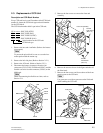
9. Remove the two screws of the front unit assembly
shown in the figure and the two screws of the rear
plate, and then remove the top chassis.
10. To reattach, perform in the reverse order of steps 1 to
9.
MB board
Diagram of harness routing on the MB board
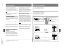
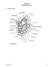
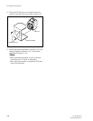
2-2. Removal/Attachment of Cabinet