


3-14
DXC-D35/D35WS(UC)
DXC-D35P/D35WSP(CE) V1
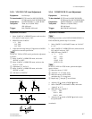
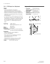
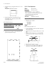
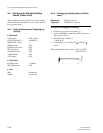
3. Adjust the lens iris to bring the white level “A” to 70
±2 IRE.
Test point: VIDEO OUT connector
4. In the following items, by pressing the UP or
DOWN switches, adjust the waveform of the
oscilloscope to be flat.
GND: TP38/EX-490 board
Item Test point Specification
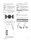
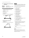
R W. SHAD CL101
G W. SHAD CL201
B W. SHAD CL301
5. If the lens has an extender, set the extender ON and
perform the adjustment of step 4.
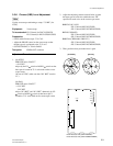
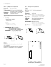
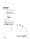
3-3-14. Flare Adjustment
Object: Grayscale chart
Equipment: Waveform monitor
Preparation:
. OUTPUT/DL/DCC + switch: CAM/DCC +
. Select a large lens iris and shoot the grayscale chart
covering fully the underscanned frame.
(Refer to Section 3-1-4.)
Test point: VIDEO OUT connector
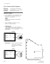
Adjustment Procedure
1. SERVICE menu “PAGE 3”
→ R FLARE: x
G FLARE: 5
B FLARE: x
n
Make sure that “G FLARE” is “5”.
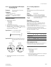
2. Push the WHT/BLK switch in the “BLK” direction to
make a black balance.
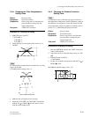
3. Adjust the lens iris to bring the white level to A = 100
IRE.
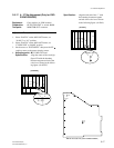
4. With the W. BAL switch set to “A”, push the WHT/
BLK switch in the “WHT” direction to make a white
balance.
5. Make the lens iris large by two steps.
6. Adjust the flare with UP and DOWN switches
alternatively to minimize the carrier leakage level.
3-3. Camera Adjustment
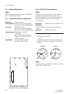
CL101
CL201
CL301
1
2
3
4
5
6
E
FG
H
VA-169 board (B side) (DXC-D35/D35P)
VA-185 board (B side) (DXC-D35WS/D35WSP)