


1-33
DXC-D35/D35WS(UC)
DXC-D35P/D35WSP(CE) V1
64
Chapter 4 Viewfinder Screen Indications and Menus
Chapter 4 Viewfinder Screen Indications and Menus
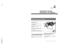
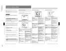
Viewfinder Advanced Menu
Bring up the advanced menu pages by setting the
POWER switch to ON while pressing the UP/ON
button up (see page 52).
There are up to 15 advanced menu pages (the number
displayed depends on the switch settings and the type
of connected VTR).
Note on EZ mode
When the camera is in EZ mode, the advanced menu
does not appear. Release the EZ mode beforehand.
(See page 14.)
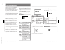
Advanced Menu Operations
To change the page
Move the cursor to the menu number, then press the
UP/ON button or the DOWN/OFF button.
Pressing the UP/ON button displays the previous page
and pressing the DOWN/OFF button displays the next
page. Pressing the DOWN/OFF button when the last
page is being displayed returns the display to the first
page.
To select items in a page
Press the MENU/STATUS switch to move the cursor
among the menu items.
To change settings
This operation is the same as for the basic menus.
For a description of basic menu operations, see page 58.
To return to the normal indications
Move the cursor to EXIT MENU, then press the UP/
ON button.
Contents and Settings of Each
Page
Each page’s contents and settings are described below.
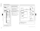
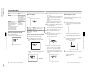
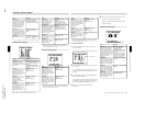
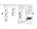
Advanced menu page 1
Use this page to return all advanced menu settings to
their factory preset values.
For details of this operation, see “Displaying the advanced
menu and switching to the normal indications” (page 52).
Advanced menu page 2
Item
Settings
GAIN
This sets gain values for the positions of the GAIN switch.
The HIGH, MID, and LOW values must be set so that LOW
< MID < HIGH.
MID
Sets the M position.
0 dB, 3 dB, 6 dB, 9 dB
(normal value), 12 dB, 18
dB, 18 dB + DPR, 24 dB, 24
dB + DPR
LOW
Sets the L position.
–3 dB, 0 dB (normal
value), 3 dB, 6 dB, 9 dB, 12
dB, 18 dB, 18 dB + DPR, 24
dB
HIGH
Sets the H position.
3 dB, 6 dB, 9 dB, 12 dB, 18
dB (normal value), 18 dB +
DPR, 24 dB, 24 dB + DPR,
HYPER GAIN
HYPER
Sets gain value when the
HYPER GAIN is selected.
36 dB (normal value), 42
dB
DL
Sets DynaLatitude function
ON/OFF.
This setting is valid only
when the OUTPUT/DL/
DCC+ switch has been set to
DL.
ON (normal value), OFF
When set to ON, the amount
of DynaLatitude effects is
set in basic menu page 3
(see page 59).
Chapter 4 Viewfinder Screen Indications and Menus
65
Chapter 4 Viewfinder Screen Indications and Menus
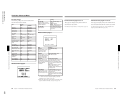
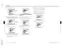
Advanced menu page 3
a) For DXC-D35P/D35WSPL: EBU75
Item
AWB MEM
Selects whether or not to
make the FILTER knob
settings (1 to 4) correspond
to separate white balance
adjustment values stored in
memory.
2 (normal value): No
correspondence with FILTER
knob settings. Only two
adjustment values (A and B)
are stored in memory.
2 × 4FL: Correspondence
with FILTER knob settings.
Each of the four knob
settings can be used to set A
and B adjustment values, for
a total of eight settings.
TONE
Selects whether or not to
output a 1-kHz audio signal
with the color bars when the
OUTPUT/DL/DCC+ has
been set to BARS.
ON (normal value): Output
audio signal.
OFF: Do not output audio
signal.
BARS
Selects normal width or
narrower width for color
bars.
SMPTE (normal value for
DXC-D35/D35WSL):
Normal width
EBU75 (normal value for
DXC-D35P/D35WSPL): EBU
75%
EBU100 (for DXC-D35P/
D35WSPL): EBU 100%
SPLIT (for DXC-D35P/
D35WSPL): Not for normal
operation
SNG: Narrower than normal
(used for satellite
communications, etc.)
REMOTE1
Sets a function for position 1
of a switch connected to the
REMOTE1 connector.
REC (normal value):
Specifies recording start/stop
MARK: Specifies a Mark IN/
OUT point.
CUE: Specifies a cue point.
NG: Specifies NG/OK.
REMOTE2
Sets a function for position 2
of a switch connected to the
REMOTE1 connector.
9600, 38400 (normal value)
REC: Specifies recording
start/stop.
MARK (normal value):
Specifies a Mark IN/OUT
point.
CUE: Specifies a cue point
NG: Specifies NG/OK.
Settings
BAUD RATE
Sets a baud rate for a
computer connected to the
REMOTE connector 2 (to be
supported in future version).
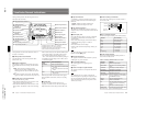
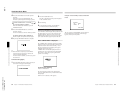
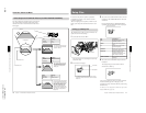
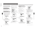
Advanced menu page 4
c
PAGE4 (NEXT
c
V
PREV
c
v
)
MARKER : CENT/90%
LIMITS : OFF
ZEBRA : 1
ZEBRA1 : 70IRE
VF S DTL: ±0
VF TALLY:
×
2
VF PLAY : Y
LENS SEL: 1
EXIT MENU (YES
c
v)
a) For DXC-D35P/D35WSPL: 70%
Item
MARKER
Selects ON/OFF setting for
center marker, size setting
(percentage of viewfinder
screen area), and display
ON/OFF setting.
CENT/90% (normal value):
Displays center marker and
safety zone marker at 90%
size.
CENT/80%: Displays center
marker and safety zone
marker at 80% size.
90%: Displays only safety
zone marker at 90% size.
80%: Displays only safety
zone marker at 80% size.
CENT: Displays only center
marker.
ZEBRA
Selects type of zebra pattern
display.
1 (normal value): Displays
the zebra pattern over parts
having a video level.
between 70 and 90 IRE (or
70 and 90%).
Use the next item (ZEBRA1)
to select the base level.
2: Displays the zebra pattern
over parts having video
levels of 100 IRE or above
( or 100% or above).
1/2: Dual display (both 1
and 2)
ZEBRA1
Sets base level for zebra
pattern 1.
70 IRE (normal value) to 90
IRE or 70% (normal value)
to 90%
Can be set for each IRE
step or 1% step.
VF S DTL
Sets the detail level of
images on the viewfinder
screen (displayed only when
a viewfinder other than the
DXF-701/701CE/701WS/
701WSCE/801/801CE is
attached).
–99 to ±0 (normal value) to
+99
Negative values set softer
edges and positive values
set sharper edges.
Settings
(continued)
LIMITS (For DXC-D35WSL/
D35WSPL)
Selects the safety zone size
when the scan size is 16:9.
OFF (normal
value):FDepends on the
scan size.
4:3, 13:9, 14:9, 15:9
a)
a)