


3-15
DXC-D35/D35WS(UC)
DXC-D35P/D35WSP(CE) V1
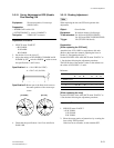
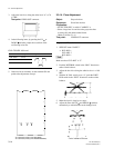
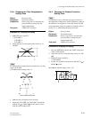
3-3-15. MIC Level/MIC Level IND Adjustment
Equipment: Oscilloscope
Preparation: OUTPUT/DL/DCC+ switch: BARS
Adjustment Procedure
MIC Level Adjustment
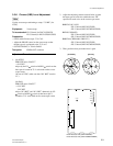
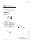
Test point:
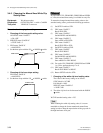
CL201 (GND: Capacitor C202 + side)
/MB-629 board (for DXC-D35/D35P)
/MB-785 board
(for DXC-D35WS/D35WSP)
Adjusting point: 1RV201
/MB-629 board (for DXC-D35/D35P)
/MB-785 board (for DXC-D35WS/D35WSP)
Specification:
A = 110 ±5 mV
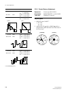
MIC Level IND Adjustment
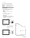
1. SERVICE menu “PAGE 17”
→ MIC ADJ
2. Adjust by the DOWN switch, and stop at the point
where the mark just appears on the monitor screen.
3. Adjust by the UP switch, and stop at the point
where the mark just disappears on the monitor
screen.
4. Set the DOWN switch at the five-descending
position from the point the mark disappears.
A
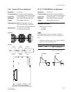
3-3. Camera Adjustment
CV1
CV3 (DXC-D35WS/D35WSP only)
B
C
D
E
F
G
6
4
3
2
1
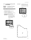
MB-629 board (B side) (DXC-D35/D35P)
MB-785 board (B side) (DXC-D35WS/D35WSP)
5
CL201
A
RV201
C202
+