


1-11
DXC-D35/D35WS(UC)
DXC-D35P/D35WSP(CE) V1
Chapter 1 Overview
20
Chapter 1 Overview
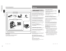
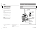
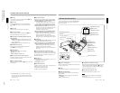
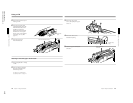
Location and Function of Parts
1 Iris ring
For manual iris control, set the IRIS selector qd to the
“M” position, and turn this ring.
2 Zoom ring
For direct manual zoom control, set the ZOOM
selector 7 to the “MANU.” position, and turn this
ring.
3 Focus ring
Turn this ring to focus the lens on the subject.
4 M (close-up) button
For close-up work, turn the MACRO ring 6 while
holding this button down. (See page 91.)
5 F.B (flange focal length) adjustment ring and
F.B fixing knob
F.B adjustment ring : To adjust the flange focal
length, loosen the F.B fixing knob, then turn the
ring. (See page 89.)
F.B fixing knob: Fixes the F.B adjustment ring.
6 MACRO (close-up) ring
For close-up, turn this ring while holding the M
button 4 down. (See page 91.)
7 ZOOM selector
This selects the mode of zoom operation.
SERVO: power zoom
MANU. (manual): manual zoom
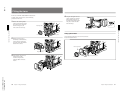
8 Zoom remote control connector (8-pin)
Connect the optional LO-26 lens remote control unit
for remote control of zooming.
9 Lens connector (12-pin)
Connect to the LENS connector (qa on page 18) of the
Camera Head.
0 RET (return) button
This allows you to check the video signal as follows.
When operating with a portable VTR connected
via other equipment: when the VTR is in
recording, pressing this button connects the E-E
video signal1) from the VTR to the viewfinder.
When operating with a DSR-1/1P or PVV-3/3P
mounted on the camera head: when the VTR is in
recording pause mode, press this button to review
the last few seconds of the recording in the
viewfinder (recording review).
When operating with a CCU-M5/M5P/M7/M7P
Camera Control Unit connected: pressing this
button connects the return video signal from the
camera control unit to the viewfinder.
When this button is not pressed, the viewfinder
displays the video signal captured by the camera.
qa VTR button
When operating with a VTR: this button starts and
stops recording, and once more to stop.
When operating with a CCU-M5/M5P/M7/M7P
Camera Control Unit connected: pressing this
button connects the return video signal from the
camera control unit to the viewfinder.
(Starting and stopping recording is controlled on
the VTR.)
qs Instant automatic iris adjustment button
While using manual iris control, press this button to
switch temporarily to the automatic iris control setting.
The automatic setting is maintained as long as you
hold the button down.
qd IRIS selector
This selects the mode of iris operation. (See page 14.)
A (automatic): automatic iris
M (manual): manual iris
qf Motorized zoom lever
Use this to carry out a power zoom. Pressing the lever
harder increases the zoom speed.
W end: zoom toward wide angle
T end: zoom toward telephoto
1) E-E video signal: “electric-to-electric” video signal.
This is the input video signal which has passed through
internal electrical circuits, but has not been converted to
a magnetic signal.
..........................................................................................................................................................................................................
Chapter 1 Overview
Chapter 1 Overview
21
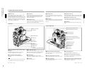
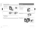
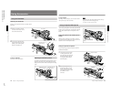
DXF-801/801CE Viewfinder
SHUTTER GAIN UP
TAKE BATTREC
TALLY
HIGH LOW OFF
LIGHT
3LIGHT switch and light
4 TAKE/TALLY indicator
5 BATT indicator
6 REC/TALLY indicators
7 GAIN UP indicator
8 SHUTTER indicator
9 PEAKING control
0 CONTRAST control
qa Tally lamp
qs BRIGHT control
qd Eyepiece release catch
qf TALLY switch
qg DISPLAY switch
qh Viewfinder connector
Eye cup
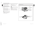
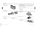
1 Eyepiece focusing knob
2 Stopper
Microphone holding screw
Microphone holder
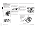
1 Eyepiece focusing knob
Turn this to adjust the viewfinder focus to match your
eyesight. (See page 88.)
2 Stopper
Lift up when detaching the viewfinder (See page 32).
3 LIGHT switch and light
The light lights the lens and the switch controls the
light as follows.
HIGH/LOW: Turn the light on and control the
brightness.
OFF: Turns the lights off.
4 TAKE/TALLY indicator (orange)
When using the ClipLink function while shooting, this
indicator lights when the TAKE button (7 on page
17) has been pressed to set a Mark IN point and goes
out when a Mark OUT point is set.
5 BATT (battery) indicator (red)
This lights when the battery capacity is low.
Note
When using a camera control unit, this indicator
flashes when
you operate the controls, but this is not a malfunction.
You can switch the scan size of the DXF-801/801CE
in accordance with the aspect ratio selected on the
camera or camcorder.
Microphone