


15
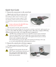
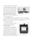
3. Connect the AC power to the control unit
Use only an approved power cord with a plug
appropriate for the power receptacles of the region.
e camera has an external universal power adapter,
able to operate from any AC voltage between 100
and 240 volts nominal, 47 to 63 Hz single phase,
without changing switches or jumpers. e camera
consumes a maximum of about 60 watts of power,
and should be operated from the same circuit sup-
plying power to the computer connected to the
camera. Approved extension cords may be used to
supply power to the camera over considerable distances.
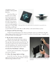
4. Turn on the digital camera
Turn on the digital camera with the switch on the control unit. e Power LED will light green
to indicate the unit has been turned on. When the Status LED next to the power switch goes out the
digital camera is ready. Also check the LED on the insert, next to the cable connector. e LED will
flash green every few seconds to indicate a good connection with the control unit.
5. Turn on the host computer
Turn on the host computer. While the computer
is starting up, Steps 6 through 8 can be completed.
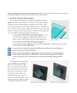
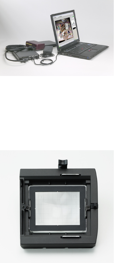
6. Install the viewing overlay on the
camera’s ground glass
e scanning insert covers an image area of 72
x 96 mm. (2.83 x 3.78 in.), slightly smaller than
standard 4x5 sheet film, centered in the overall image
area. Several black plastic viewing masks have been
supplied with the digital camera, which can be placed
over the ground glass of your camera to indicate the
area available for digital imaging. ese masks have
a low-tack adhesive on one side, allowing them to be
secured to either the inside or outside of the ground
glass, yet easily removable. Line up the centering
notches in the inside of the mask with the center lines
Overlay mounted on a ground glass view screen.