


7-19
Appendix
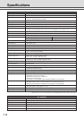
Specifications
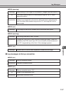
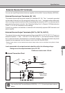
+3.3V
0.1µF
10kΩ 10kΩ
10kΩ
Internal controller
Input terminals
IN
+
, IN
–
Output terminals
OUT A, OUT B
+
–
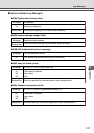
External Device I/O Terminals
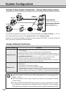
You can use Input/Output external devices together with the Multi-Terminal Module (VB-EX50).
External Device Input Terminals (IN
+
, IN
–
)
The external device input terminals consist of 2 terminals (IN
+
, IN
-
). The ‘–’ terminal is grounded
on the inside of the main unit. By connecting 2 cables to the + and ‘–’ terminals and then electrically
short-circuiting across the terminals (ON) or separating the connection (OFF), an interrupt can be
generated for the internal controller. See “Schedule Setting Tool” in Chapter 4 “VB Administration
Tools” (→ P.4-27) for information on the settings.
Connect any sensors and switches to terminals with electrically separate GND terminals and
power supplies.
External Device Output Terminals (OUT A, OUT B, OUT C)
The external device output terminals consist of 3 terminals (OUT A, OUT B, OUT C). There is no
distinction between “+” and “–” with OUT A, OUT B and OUT C. The Internal controller switches
the 2 output terminals to disconnected or connected condition. The output terminals use photo
couplers and are separate from the internal circuit in the VB-C50i/VB-C50iR.
* External input status can be checked and external output status can be controlled using Admin Viewer
(→ P.4-65).
Loads connected to the output terminals should be within the following ratings:
Rating across the output terminals: Up to 50 V DC
Continuous load current: 100 mA
Internal Connection Chart
Tip
You need the Multi-Terminal Module (VB-EX50) (→ P.1-11) to set input/output external
device.