


14 PIXIS System Manual Version 2.C
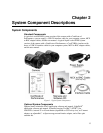
PIXIS Camera
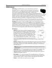
CCD Array: The PIXIS camera system offers both front- and back-
illuminated CCDs in a variety of array sizes that allow you to precisely
match the sensor to your application. Only scientific-grade devices are
used in order to ensure the highest image fidelity, resolution, and
acquisition flexibility required for scientific imaging. Princeton Instruments has
developed exclusive CCDs with unmatched quantum efficiency and low noise to offer the
utmost in sensitivity. Large full wells, square pixels, and 100% fill factors provide high
dynamic range and excellent spatial resolution. Unichrome (exclusive Princeton
Instruments technology) and other UV-enhancement coatings can be used to further
improve the quantum efficiency of these CCDs in the ultraviolet. Your choice of CCD is
already installed in the camera that you received and has been individually tested.
Cooling: Dark current is reduced in PIXIS camera systems through thermoelectric
cooling of the CCD arrays. Cooling by this method uses a four-stage Peltier cooler in
combination with circulating air or coolant. To prevent condensation and contamination
from occurring, cameras cooled this way are evacuated. Due to CCD size/packaging
differences, the lowest achievable temperature can vary from one PIXIS model to the
next. Please refer to the specific system’s data sheet for cooling performance.
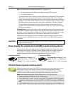
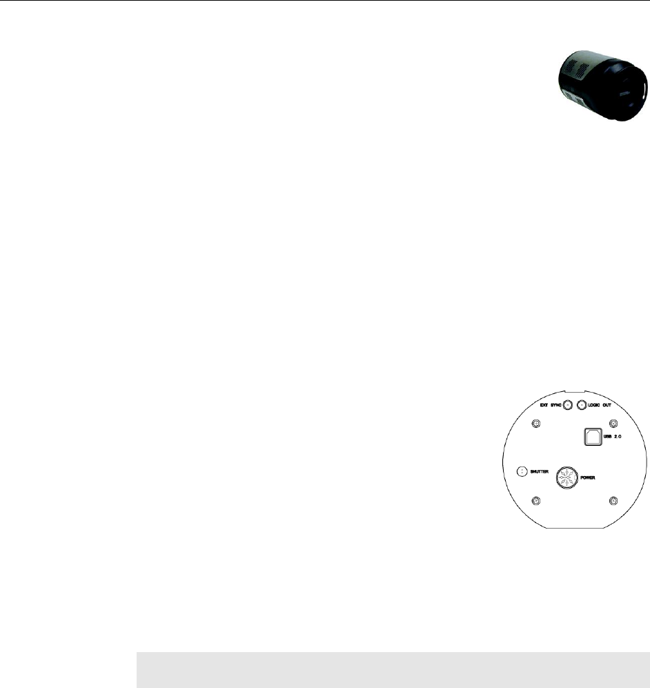
Connectors:
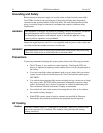
USB 2.0: Control signals and data are transmitted between
the camera and the host computer via the USB port located on
the rear of the camera. As of this printing, you can hot plug
the PIXIS camera whenever the WinX application is not
running (i.e., connect or disconnect from the camera or the
host computer while the camera is powered ON). In the
case of cameras built before November 1, 2005, you must
exit the WinX application and turn the camera power OFF
before connecting the USB cable to or disconnecting it from the camera or host
computer.
Shutter: LEMO
®
connector provides the shutter drive pulses for driving a Princeton
Instruments-supplied external shutter (for example, a shutter at the entrance slit of a
spectrograph). Camera power must be OFF before connecting to or disconnecting
from this connector.
Note: When there is an installed internal shutter, this connector cannot drive an
external shutter.
LOGIC OUT: 0 to +3.3V programmable logic level output (TTL-compatible). The
output of this connector can be programmed and can also be inverted via the
application software. For detailed information about each output signal, please see
“LOGIC OUT Control” (page 76).
EXT SYNC: 0-+3.3V logic level input (TTL-compatible) that has a 10 k pullup
resistor. Allows data acquisition and readout to be synchronized with external events.
Through software, positive or negative (default) edge triggering can be selected.
Power: 12 VDC (6.6A max) input from power supply.