


Chapter 6 Advanced Topics 73
73
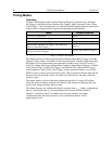
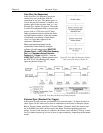
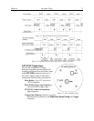
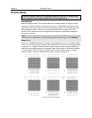
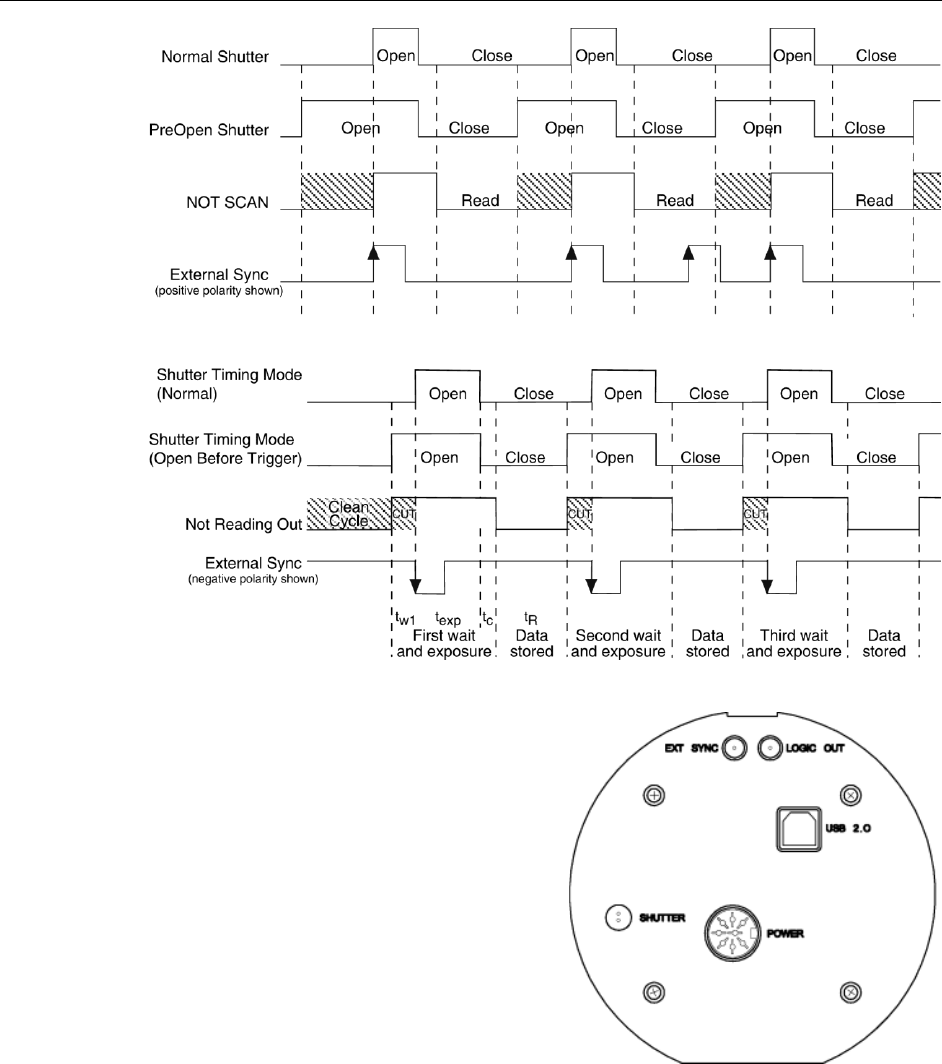
Figure 33. WinX Continuous Cleans Timing Diagram
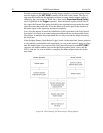
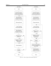
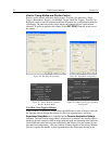
Figure 34. LightField Clean Until Trigger (CUT) Timing Diagram
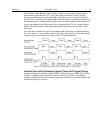
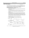
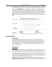
EXT SYNC Trigger Input
The selected Timing Mode {Trigger
Response} determines how the camera will
respond to an External Sync pulse that is input
at the EXT SYNC connector on the rear of
the camera. Things to keep in mind when
setting up the External Sync pulse input are:
Pulse Height: 0 to +3.3V logic levels
(TTL-compatible).
Pulse Width (trigger edge frequency):
The time between trigger edges.
EXT SYNC Connector Impedance:
High impedance.
Trigger Edge {Polarity}: Positive or negative
polarity must be indicated on the Experiment Setup|Timing tab {Trigger
expander}.
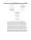
Figure 35. Rear of PIXIS Camera