


Chapter 5 Operation 65
65
Digitization (Rate)
Introduction
After gain has been applied to the signal, the Analog-to-Digital Converter (ADC)
converts that analog information (continuous amplitudes) into a digital data (quantified,
discrete steps) that can be read, displayed, and stored by the application software. The
number of bits per pixel is based on both the hardware and the settings programmed into
the camera through the software (see "Readout", page 59).
Factors associated with digitization include the digitization rate and baseline offset. The
speed at which digitization occurs is software-selectable but baseline offset is factory-set.
These factors are discussed in the following paragraphs.
Digitization Rate {Speed}
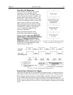
PIXIS cameras incorporate dual digitization (100 kHz/2 MHz), which means that you
have a choice of how quickly the data will be digitized. Dual digitization provides
optimum signal-to-noise ratios at both readout speeds. Because the readout noise of CCD
arrays increases with the readout rate, it is sometimes necessary to trade off readout speed
for high dynamic range. The 2 MHz conversion speed is used for the fastest possible data
collection and the 100 kHz conversion speed is used where noise performance is the
paramount concern. Switching between the conversion speeds is completely under
software control for total experiment automation.
Note: In WinX, the ADC rate can be changed on the Experiment Setup|ADC tab. In
LightField, the speed is changed on the Analog-Digital Conversion expander.
ADC Offset (Bias)
With the camera completely blocked, the CCD will collect a dark charge pattern,
dependent on the exposure time and camera temperature. The longer the exposure time
and the warmer the camera, the larger this background will appear. To minimize the
amount of this signal that gets digitized, the baseline has been offset by adding a voltage
to the signal to bring the A/D output to a non-zero value, typically 500-600 counts. This
offset value ensures that all the true variation in the signal can really be seen and not lost
below the A/D “0” value. Since the offset is added to the signal, these counts only
minimally reduce the range of the signal from 65535 (16-bit A/D) to a value in the range
of 500-600 counts lower.
Notes:
1. It is important to note that the bias level is not noise. It is a fully subtractable readout
pattern. Every device has been thoroughly tested to ensure its compliance with
Princeton Instruments' demanding specifications.
2. The ADC Offset is pre-set at the factory and is not user-changeable.
If you observe a sudden change in the baseline signal, there may be excessive humidity in
the camera vacuum enclosure. Turn off the camera and contact Princeton Instruments
Customer Support. See page 132 for contact information.
WARNING!