


76 PIXIS System Manual Version 2.C
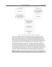
LOGIC OUT Control
The TTL-compatible logic level output (0 to +3.3 V) from the LOGIC OUT connector
on the rear panel can be used to monitor camera status and control external devices. By
default, the logic output level is high while the action is occurring. The timing of the
level changes depends on the output type selected on the Hardware
Setup|Controller/Camera tab {Trigger expander}:
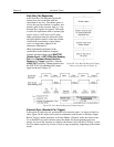
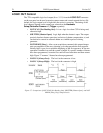
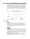
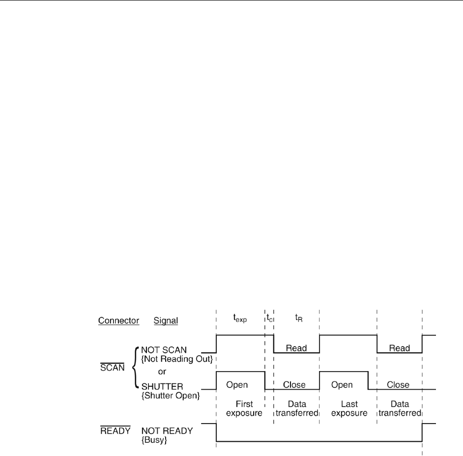
NOT SCAN {Not Reading Out}: It is at a logic low when CCD is being read;
otherwise high.
SHUTTER {Shutter Open}: Logic high when the shutter is open. The output
precisely brackets shutter-open time (exclusive of shutter compensation, t
c
) and
can be used to control an external shutter or to inhibit a pulser or timing
generator.
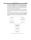
NOT READY {Busy}: After a start acquisition command, this output changes
state on completion of the array cleaning cycles that precede the first exposure.
Initially high, it goes low to mark the beginning of the first exposure. In free run
operation it remains low until the system is halted. If a specific number of frames
have been programmed, it remains low until all have been taken and then returns
high. Figure 37 assumes 3 frames have been programmed.
LOGIC 0 {Always Low}: The level at the connector is low.
LOGIC 1{Always High}: The level at the connector is high.
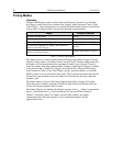
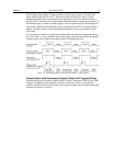
Figure 37. Comparison of NOT SCAN {Not Reading Out}, SHUTTER {Shutter Open}, and NOT
READY {Busy} Logic Output Levels