


60 PIXIS System Manual Version 2.C
Full Frame Readout
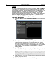
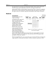
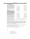
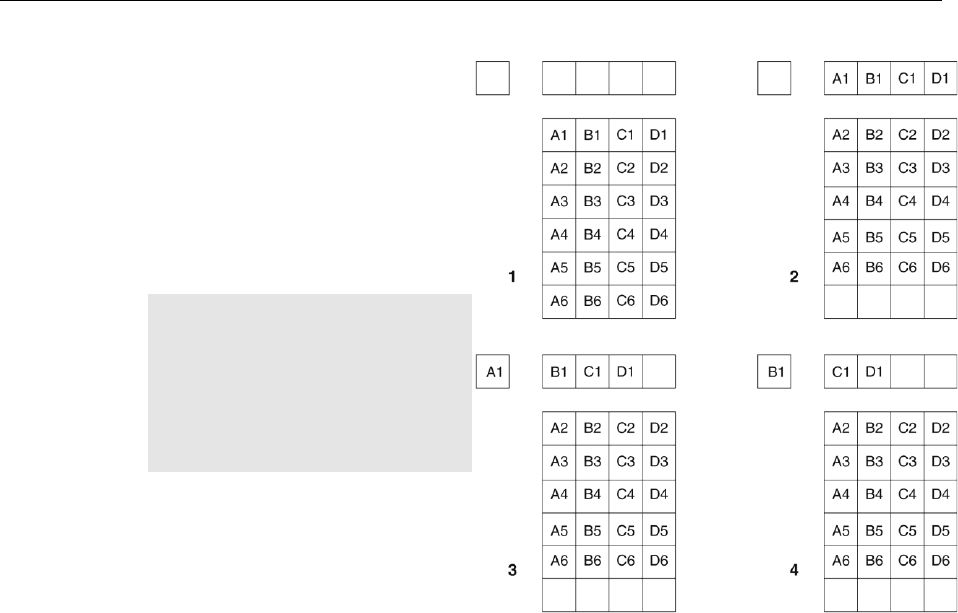
The upper left drawing in Figure 25
represents a CCD after exposure but
before the beginning of readout. The
capital letters represent different
amounts of charge, including both
signal and dark charge. This section
explains readout at full resolution,
where every pixel is digitized
separately.
Note: With PIXIS cameras you have
a choice of amplifier (low noise or
high capacity). Depending on the
selected amplifier, the shift register
may be read out to the right or to the
left. For simplicity this drawing
shows the readout to the left.
Readout of the CCD begins with the
simultaneous shifting of all pixels
one row toward the "shift register,"
in this case the row on the top. The
shift register is a single line of
pixels along the edge of the CCD,
not sensitive to light and used for
Figure 25. Full Frame at Full Resolution
readout only. Typically the shift register pixels hold twice as much charge as the pixels in
the imaging area of the CCD.
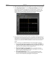
After the first row is moved into the shift register, the charge now in the shift register is
shifted toward the output node, located at one end of the shift register. As each value is
"emptied" into this node it is digitized. Only after all pixels in the first row are digitized is
the second row moved into the shift register. The order of shifting in our example is
therefore A1, B1, C1, D1, A2, B2, C2, D2, A3....
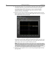
After charge is shifted out of each pixel the remaining charge is zero, meaning that the
array is immediately ready for the next exposure.
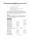
Below are the equations that determine the rate at which the CCD is read out.
The time needed to take a full frame at full resolution is:
cR
ttt
exp
(1)
where
t
R
is the CCD readout time,
t
exp
is the exposure time, and
t
c
is the shutter compensation time.