


22
2. CONTROLS, INDICATORS AND CONNECTORS
PUSH
PROMPTER
OUTPUT
VTR/RM
CH-1 CH-2
Y/C OUT
TC IN TC OUT
REMO
T
DV CAMCOR
D
GY-DV55
0
MONITOR OUT
LINE OUT
INTERCOM
DC INPUT
DV
AUDIO IN
EARPHONE
DC
OUTPUT
LINE MIC
+48V
ON ON
LINE MIC
+48V
REAR
FRONT
w
q
e
ru
i
y
t
o
!1
!0
BREAKER
1
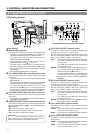
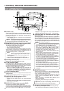
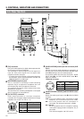
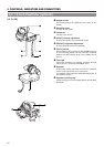
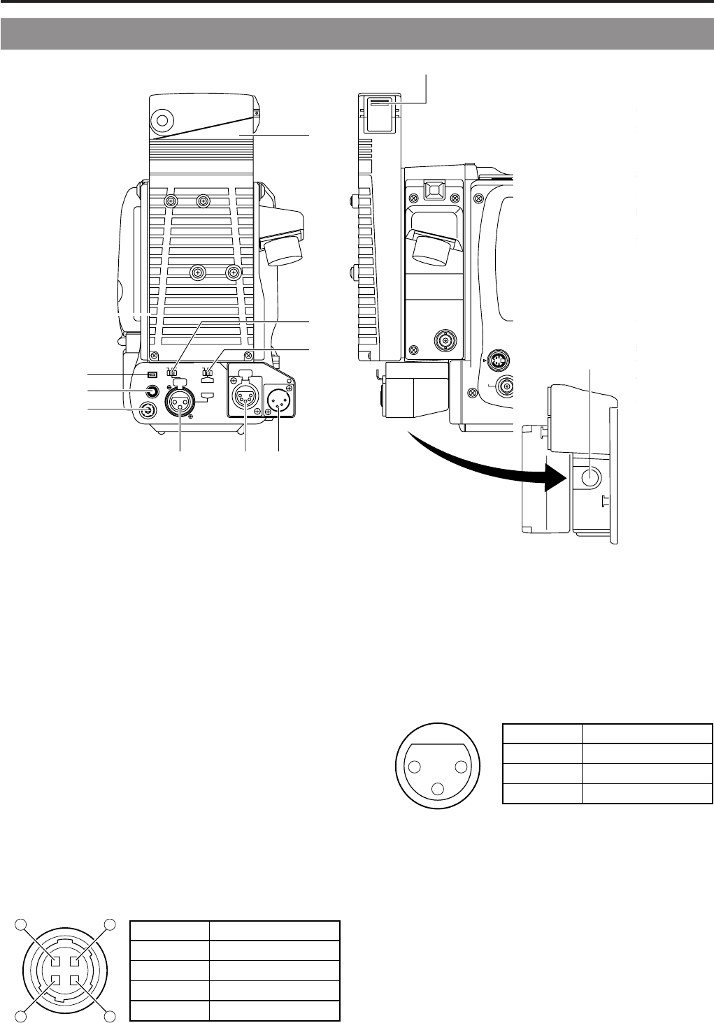
[DV] connector
Using a DV cable (optional), a digital video component with
DV connector can be connected here.
This connector is used for output of the DV signal or to
input the VCR control signal from the digital video
component with DV connector.
• To remote control the VCR with a VCR control signal from
this connector, set the VCR Setup Menu item No. 050
REMOTE SELECT to "IEEE1394".
2
[EARPHONE] earphone jack
This is a mini-jack for connecting an audio monitoring
earphone. Plug in an earphone or headphone with a 3.5
mm diameter plug. Audio is outputted in monaural.
The earphone can also be used to monitor alarm tones
depending on situations.
The sound from the monitoring loudspeaker is interrupted
when an earphone is connected here.
3
[DC OUTPUT] connector
Power output connector to a wireless microphone
transmitter, etc. The supply voltage is identical to the voltage
supplied to the unit (DC 12V max. 0.1 A).
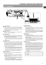
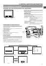
4
[AUDIO IN REAR] audio input rear connector (XLR
3-pin)
Connect the external audio equipment or microphone to
this connector. Set the AUDIO IN REAR LINE/MIC select
switch
5
according to the connected equipment.
To record the audio of this connector, set the CH-1 AUDIO
INPUT switch
7
or the CH-2 AUDIO INPUT switch
8
on
page 14 to "REAR".
(AUDIO IN connector)
5
[AUDIO IN REAR LINE/MIC] AUDIO IN REAR select
switch
Selects the audio signal input to the
4
AUDIO IN REAR
connector.
LINE : Set to this position when connected to audio
equipment, etc. The reference input level is +4 dBs.
MIC : Set to this position when the microphone is
connected. The reference input level is -60 dBs.
MIC +48V ON:
Set to this position when the microphone requiring
+48 V power supply (phantom microphone, etc.) is
connected.
This connector supplies +48 V DC current.
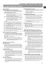
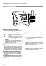
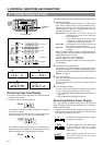
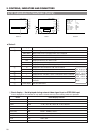
(Surface profile)
14
23
No. Signal
GND
—
—
DC +12V (power through)
1
2
3
4
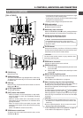
2-6 Rear Section
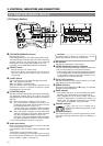
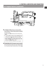
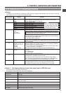
Bottom side
No. Signal
GND
HOT
COLD
1
2
3
2
1
3