


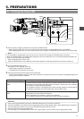
6. SETTING AND ADJUSTMENTS BEFORE SHOOTING
49
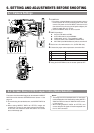
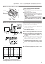
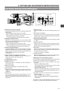
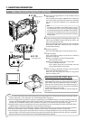
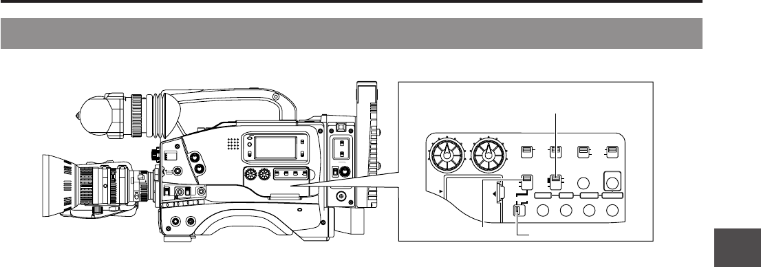
6-8 Switch Settings of the VCR Section
Ⅲ Selecting the video input signals
Video signals recorded on this unit is selected using the VTR
INPUT switch.
• When recording camera images, set to CAM.
• When recording composite video signals from the
GENLOCK/AUX IN connector, set to AUX.
☞ See “Recording External Video Signals” on page 57
Ⅲ Selecting the VCR to record
Whether to record using this unit or the external VCR
connected to the VTR/RM multi-pin connector is selected
using the VTR SELECT switch.
• When recording with this unit only, set to INT.
• When recording with an external VCR, set to EXT or PARA.
☞ See “Recording with an external VCR” on page 58
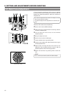
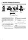
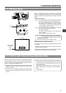
Ⅲ Audio input signal selection
Use the AUDIO INPUT switch to select whether the sound
recorded on audio channel 1 or 2 is the sound from the AUDIO
INPUT connector on the front section or the sound from the
AUDIO INPUT connector on the rear section.
☞ See page 50.
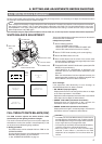
Ⅲ Audio recording level adjustment selection
Select "AUTO" or "MANUAL" for the recording level
adjustment mode for each audio channel.
☞ See page 51.
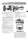
Ⅲ VCR Setup Menu setting
● REMOTE SELECT
Confirm that "LOCAL" is selected if you want to operate on
the GY-DV550 only.
● BACK TALLY MODE
Select the lightning pattern of the BACK TALLY lamp.
● INPUT SELECT
Select the input video signal (camera images or DV terminal
images). To record the GY-DV550’s camera image, set to
“CAMERA”.
● LOW CUT IN
For each audio input connector, select whether or not the
lower frequency components of the audio signal are cut.
Set to this position to eliminate the wind noise of the
microphone.
● SAMPLING RATE
Select the sampling rate for audio recording (48 kHz or 32
kHz).
● CH1 FRONT VR ENABLE
Set whether or not the front section's audio volume control
should be used. The front section's audio volume control only
affects the CH1 audio channel.
● AUDIO REF. SIGNAL LEVEL
The reference recording level to the tape is selected (-20dB
or -12dB
● LONG PAUSE TIME
Select the time (in minutes) until the GY-DV550 enters the
tape protection mode (drum rotation stops) when the record-
pause mode is continued for long time.
● SSF MODE
Select the mode of the S.S.F. (Super Scene Finder) function.
S.S.F. function: Stores the time code of desired scenes or
cue points in the unit's memory.
☞ See “S.S.F. function” on page 66.
● DISPLAY SELECT
Select the counter display (time code or date/time indication)
when the COUNTER switch is set to “TC” or “UB”.
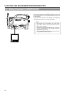
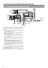
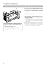
Ⅲ Setting the time code recording function
The GY-DV550 records SMPTE-standard time code during
recording. Set the switches according to applications.
● To record a time code as set in the built-in time code
generator:
• Set the TC GENE switch to REC.
This position allows you to record continuous time codes
when recording scenes one after another.
• VCR Setup Menu setting
Select the time code generator’s framing mode as drop
frame or non-drop using the VCR Setup Menu item No. 416
“MON DROP/DROP”.
● To record a time code in continuation of the existing time
code on the tape:
• Set the TC GENE switch to REGEN.
• Set the VCR Setup Menu item No. 302 BACK SPACE to
“STANDARD”.
For details on the time code operations including time code
presetting, see "TIME CODE OPERATION" on page 62.
SHUTTERSTATUS
MENU
FILTER
3200k
1
5600k+1/8ND
2
5600k+1/64ND
3
ALARM
MONITOR
OPERATE
NG
GAIN
OUTPUT
WHT.BAL
VTR
ON OFF
AUTO IRIS
LOLUX
BACK L
NORMAL
SPOT L
STRETCH
NORMAL
COMPRESS
LIGHT
ON
OFF
COUNTER
AUDIO SELECT
MANUAL
AUTO
CH-1 CH-2 CH-1 CH-2
REAR
FRONT
RM
AUDIO INPUT
MODE
CTL
TC
UB
CH-1
MIX
CH-2
RESET
OPERATE/WARNING
MONITOR
SELECT
CH-1
AUDIO
LEVEL
CH-2
VTR
ON
OFF
INCOM
MIC
INCOM
MIC
LEVEL
POWER
OFFRM
DC IN
/BATT.
CALL
CARBON
DYNAMIC
FULL AUTO BLACK
AUDIO SELECT
CONTINUE
MANUAL
AUTO
INT
EXT
AUX
GROUP ITEM SELECT DATA SET
HOLD SHIFT ADVANCE PRESET
CAM
CH-1 CH-2 CH-1 CH-2
REAR
FRONT
AUDIO INPUT
CH-1
SEE
INSTR-
UCTION
MANUAL
CH-2
AUDIO
LEVEL
VTR SELECT
VTR INPUT
PARA
REC
FREE
PRST
REGEN
TC GENE.
MENU
LITHIUM BATT.
VTR SELECT switch VTR INPUT switch
TC GENE switch