


7. SHOOTING OPERATION
59
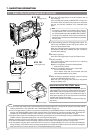
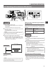
1.
Set the OPERATE switch to ON.
• Camera images will be outputted from the VTR/RM multi-
pin connector.
• Standby signal will be sent to the external VCR.
2.
For parallel recording (this unit and external VCR), set the
VTR switch to STBY.
• This unit will enter the standby mode.
3.
Press the VTR trigger button to start recording.
Ⅲ To pause recording, press the VTR trigger button again.
• During recording, the REC/ALARM lamp on the
viewfinder will light. In addition, “REC 2” will appear on
status screen 1 of the viewfinder.
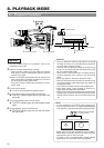
7-6 Recording with an External VCR (Cont'd)
Operation
Memo:
The external VCR will not enter the SAVE mode even
when setting the VTR switch to SAVE.
External VCR status
REC 2 lamp on: Recording
REC 2 lamp flashing: Alarm
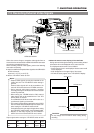
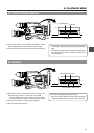
About the return video/audio signal monitor of
the external VCR
With this unit, the return video signals and audio signals of the
external VCR can be checked through the VTR/RM multi-pin
connector.
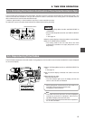
1.
Set the VTR SELECT switch to EXT.
2.
Press the RET button on the lens section.
The return video and audio of the external VCR can be
monitored wile the RET is held down.
Return video: Can be monitored on the viewfinder.
Return audio: Can be monitored using speakers or
earphones.
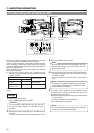
About the external VCR alarm display
• When the alarm of the external VCR is on, the REC/ALARM
lamp of the viewfinder will flash. Furthermore, the REC 2
indicator on the viewfinder status screen 1 will also flash.
• The battery alarm of the external VCR will not be displayed
on this unit.
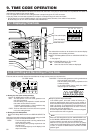
Operation
Memo:
• During monitoring of the return audio, the volume can
be adjusted using MONITOR volume.
However, the return audio is not displayed on the
audio level meter of the display. The AUDIO MONITOR
switch is also disabled.
External VCR mode Return signals
During playback Playback images and playback
sound
Other than playback E-E images and E-E sound of
external VCR
Do not change the VTR SELECT switch setting during
recording.
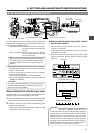
CAUTION:
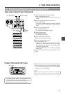
SHUTTERSTATUS
MENU
FILTER
3200k
1
5600k+1/8ND
2
5600k+1/64ND
3
ALARM
MONITOR
OPERATE
NG
GAIN
OUTP
UT
WHT.BAL
VTR
ON OFF
AUTO IRIS
LOLUX
BACK L
NORMAL
SPOT L
STRETCH
NORMAL
COMPRESS
LIGHT
ON
OFF
COUNTER
AUDIO SELECT
MANUAL
AUTO
CH-1 CH-2 CH-1 CH-2
REAR
FRONT
RM
AUDIO INPUT
MODE
CTL
TC
UB
CH-1
MIX
CH-2
RESET
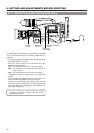
OPERATE/WARNING
MONITOR
SELECT
CH-1
AUDIO
LEVEL
CH-2
VTR
ON
OFF
INCOM
MIC
INCOM
MIC
LEVEL
POWER
OFFRM
DC IN
/BATT.
CALL
CARBON
DYNAMIC
FULL AUTO BLACK
AUDIO SELECT
CONTINUE
MANUAL
AUTO
INT
EXT
AUX
GROUP ITEM SELECT DATA SET
HOLD SHIFT ADVANCE PRESET
CAM
CH-1 CH-2 CH-1 CH-2
REAR
FRONT
AUDIO INPUT
CH-1
SEE
INSTR-
UCTION
MANUAL
CH-2
AUDIO
LEVEL
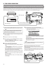
VTR SELECT
VTR INPUT
PARA
REC
FREE
PRST
REGEN
TC GENE.
MENU
LITHIUM BATT.
ACCU -FOCUS
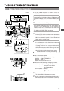
G
F
I
F5.6
STBY
REC2
EXT
4V21.>60
B
CH1-----+--
CH2-----+--
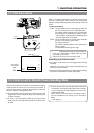
SD
:213C
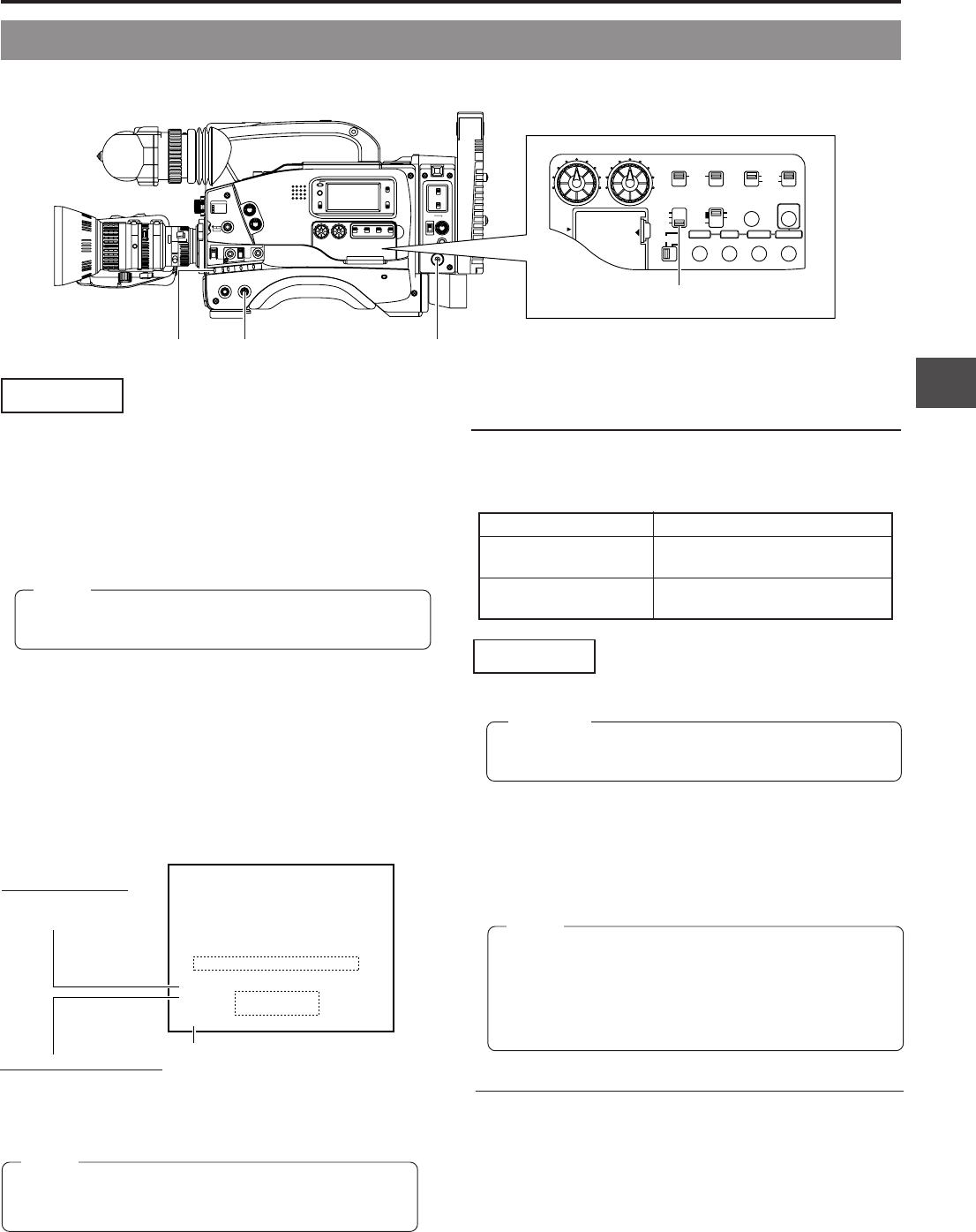
Status screen 1
Status display of this unit’s VCR
VCR SELECT information
EXT: External VCR
PARA: External VCR + this unit
INT: This unit
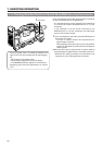
VTR switch OPERATE switch
POWER switch
VTR SELECT switch
Memo:
When the VTR SELECT switch is set to EXT, the TALLY
lamp turns on during recording.