


9. TIME CODE OPERATION
64
9-3
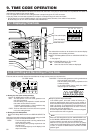
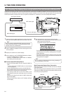
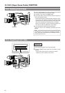
Recording Time Codes by Slave-Locking the Built-in Time Code Generator with External TCG
The built-in time code generator can be synchronized (slave-locked) with the SMPTE-standard LTC time code signal which is input
through the TC IN connector. Once the slave locking has been carried out, the built-in time code generator runs even when the
external time code input stops. Even when the power is switched off, it continues to run on the backup lithium battery.
1.
Input the reference video signal into the external time code
generator and the GENLOCK/AUX IN connector of this unit.
2.
Input the SMPTE standard LTC time code signal into the
TC IN connector.
3.
Display time code on the counter display.
4.
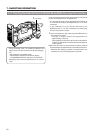
Set the switches in the TC GENERATOR block as follows.
• Set the TC GENE switch to “FREE”.
* While the TC GENE switch is set to “REC” or “REGEN”,
slave-locking will not take place.
Ⅵ Set the related VCR Setup Menus.
• Set the VCR Setup Menu item No. 398 SSF MODE to
“OFF”.
* If set to CUE mode or MARK mode, the slave-locking
will not take place.
• Set the VCR Setup Menu item No. 403 U-BIT SLAVE.
Set to “TC&UB” when the user’s bits should also be slave-
locked with the external time code generator.
• The framing mode will be the same mode as the
automatically entered time code (drop frame of non-drop
frame).
During the non-drop frame mode, the NDF indicator will
light on the display.
During the drop frame mode, the DF indicator will light
on the display.
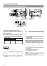
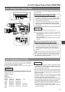
5.
Set and operate the external time code generator.
➡ The built-in time code generator is slave-locked with the
input external time code data.
The SLAVE indicator lights on the display.
* If the external time code generator phase is not genlocked
with the phase of the camera video signals, the “SLAVE”
display will flicker.
• Once slave locking has been made, the built-in time code
generator keeps on running even when the external time
code generator is stopped.
Note :
Do not connect or disconnect slaves during recording as
this may disturb the servo lock.
Note :
When the power is switched ON while external sync signal
is input, the screen moves in a vertical direction for a few
seconds. This is not a malfunction.
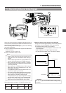
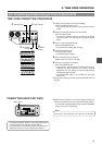
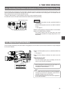
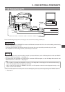
Multi-Camcorder Master-Slave Connection
When there is only one slave GY-DV550, connect it as indicated
in the figure below.
When connecting several GY-DV550s as slaves, input the REF
video signal to GENLOCK/AUX IN connectors of all these units
from the sync signal generator.
PUSH
PROMPTER
OUTPUT
VTR/RM
CH-1 CH-2
Y/C OUT
TC IN TC OUT
REMOTE
GENLOCK/AUX IN
DV CAMCORDER
GY-DV550
VIDEO OUT
AUDIO IN
FRONT
LENS
MONITOR OUT
LINE OUT
Sync signal generator
External time code generator
REF Video signal
REF Video signal
LTC time code signal
GENLOCK/AUX
IN connector
H
SLAVE
M S F
PUSH
PROMPTER
OUTPUT
VTR/RM
CH-1 CH-2
Y/C OUT
TC IN TC OUT
REMOTE
GENLOCK/AUX IN
DV CAMCORDER
GY-DV550
VIDEO OUT
AUDIO IN
FRONT
LENS
MONITOR OUT
LINE OUT
PUSH
PROMPTER
OUTPUT
VTR/RM
CH-1 CH-2
Y/C OUT
TC IN TC OUT
REMOTE
GENLOCK/AUX IN
DV CAMCORDER
GY-DV550
VIDEO OUT
AUDIO IN
FRONT
LENS
MONITOR OUT
LINE OUT
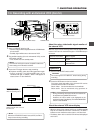
MONITOR OUT
TC OUT TC IN
GENLOCK/
AUX IN
MASTER SLAVE