


14. OTHERS
96
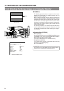
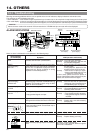
Warnings concerning problems with the unit are provide in the form of indicators, display indications and monitor tones.
The warnings are of the following two types.
• Alarm indications :
These indications are given to provide warning on the status of the unit, for example when the tape or battery pack should be replaced.
• Error code display : In case an error occurs during operation, the unit self-diagnoses the cause and shows the diagnostics results
on the counter display. When this happens, the unit stops operation automatically or ejects the videocassette.
14-1 Troubleshooting
Alarms and error codes of the external VCR connected to the VTR/RM multi-pin connector will not be displayed.
CAUTION:
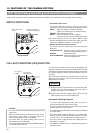
Lights in the case of troubles with the drum servo.
Lights when the input sync signal is disturbed
or the unit is subjected to physical shock.
(Displayed only during recording or during
playback of unrecorded portions.)
Lights in case of video head clogging.
(Head clogging is detected and indicated during
playback and recording check using the RET
button on the lens section.)
Improper cassette type
Lights when the lithium battery for backup of time
code generator and date/time data is exhausted.
* About 2 minutes before tape end. (The TALLY
lamp and alarm sound are activated only in
the record mode.)
* When the tape has ended completely.
When the remaining battery capacity is low.
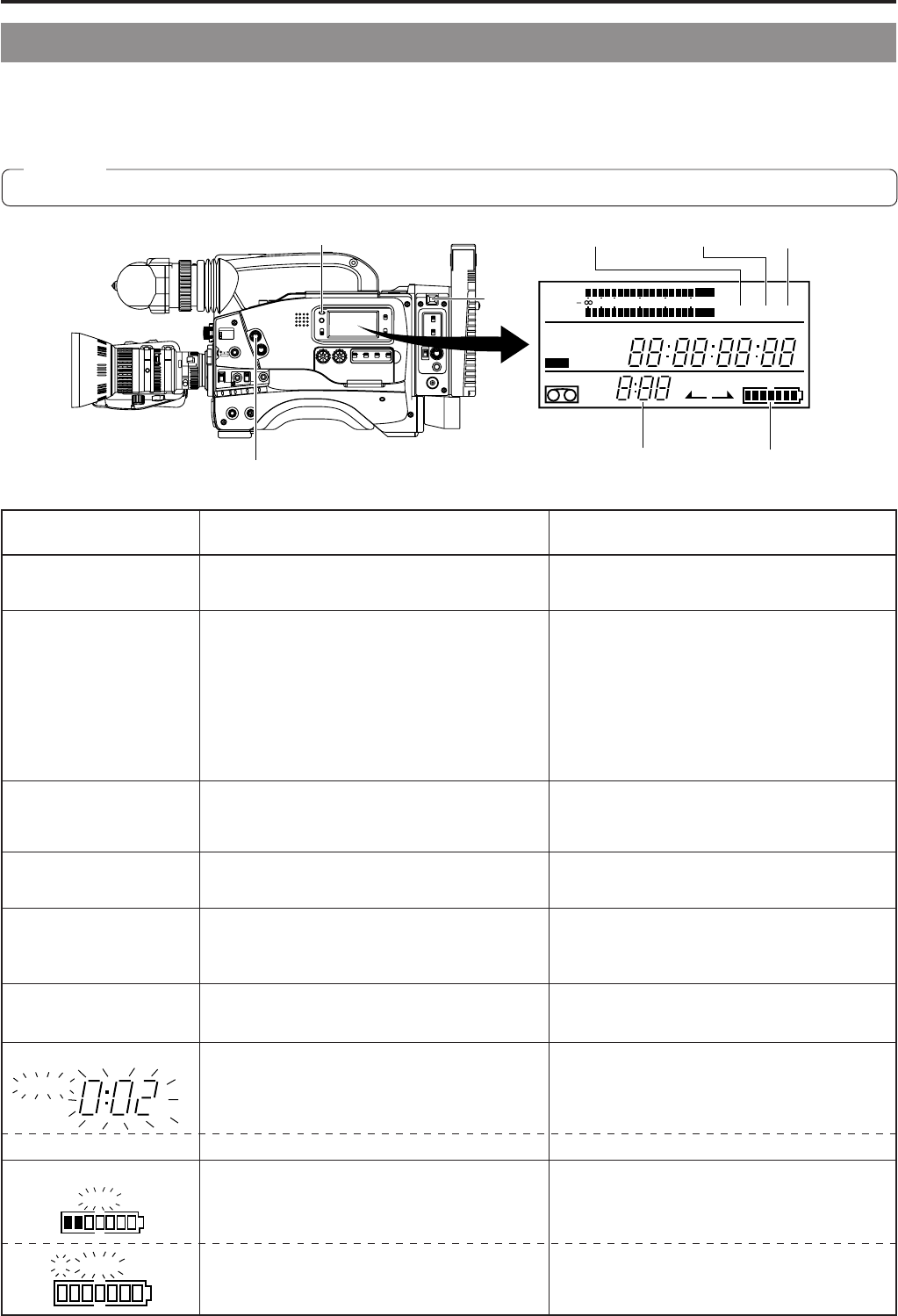
When the battery capacity drops to an insufficient
level.
Operation : Continues.
Remedy : Replace with a new lithium battery.
See page 36.
Operation : Continues.
Operation : Stops.
Operation : Continues.
Remedy : Replace battery pack early.
Operation : Stops automatically.
The camera may generate abnormal signals.
This is not a malfunction.
Operation : During recording the mode becomes
the stop mode.
During playback, playback of the
disturbed video image continues.
Remedy : • Also check the input sync signal.
• Signal is disturbed when the unit
is subject to a violent shock.
In other cases, please consult the person in
charge of professional video equipment at your
nearest JVC-authorized service agent.
Operation : Continues.
Remedy :
Clean the head with the special head
cleaning tape. (See “Precautions for Use
of Head Cleaning Tape” on page 8.)
Operation : Operation stops.
Remedy : Use recordable MiniDV cassette for
recording video and audio.
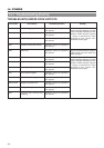
E
REV FWD
FBATT
H
HM
MSF
REMAIN
AUD LOCK
32k
CH 1
CH 2
48k
PB NDF
AUTO OFF DEW
L iRFSERVO
HOLD
SP
MENU
OVER
OVER
40 30 20 10 0
dB
WIDE
SLAVE
SHUTTERSTATUS
MENU
FILTER
3200k
1
5600k+1/8ND
2
5600k+1/64ND
3
ALARM
MONITOR
OPERATE
NG
GAIN
OUTPUT
WHT.BAL
VTR
ON OFF
AUTO IRIS
LOLUX
BACK L
NORMAL
SPOT L
STRETCH
NORMAL
COMPRESS
LIGHT
ON
OFF
COUNTER
AUDIO SELECT
MANUAL
AUTO
CH-1 CH-2 CH-1 CH-2
REAR
FRONT
RM
AUDIO INPUT
MODE
CTL
TC
UB
CH-1
MIX
CH-2
RESET
OPERATE/WARNING
MONITOR
SELECT
CH-1
AUDIO
LEVEL
CH-2
VTR
ON
OFF
INCOM
MIC
INCOM
MIC
LEVEL
POWER
OFFRM
DC IN
/BATT.
CALL
CARBON
DYNAMIC
FULL AUTO BLACK
SERVO
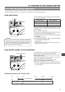
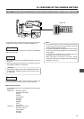
indicator
WARNING indicator
RF indicator
Li indicator
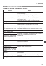
Remaining tape
time display
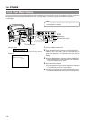
Remaining battery
power display
ALARM
TALLY
lamp
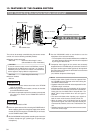
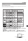
ALARM INDICATIONS
When an alarm is indicated, the unit operates in the following ways.
E BATT
Alarm Indicator
on VCR Display
Li
Remaining tape time
Remaining battery power
Symptom VCR Operation and Remedy
HM
REMAIN
E BATT
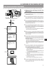
DEW Indicates dew formation (condensation). Operation : The VTR rejects operation.
Remedy : Leave the power on, and wait until
the indication disappears.
SERVO
(Counter display)
“SYnc inh”
RF
(Counter display)
“HEAd CLoG”
(Counter display)
Pc TAPE
• No signal is input to the DV connector.
• Copy-guarded signals are input.
Operation : Operation stops.
Remedy : •
Input signals to the
DV
connector.
• Copy-guarded signals cannot be
recorded.
(Counter display)
1394 inh