


12. SETUP MENU
74
OFF
CH1
CH2
CH1 &
CH2
oF
01
02
on
32K
48K
32
48
DISABLE
ENABLE
oF
on
-20dB
-12dB
20
12
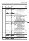
To select whether or not the low frequencies of the audio
signal from the audio input connectors are cut. Set to
ON to reduce the wind noise of the microphone.
OFF :
The CH1 and CH2 low frequencies are not cut.
CH1 : Only the low frequencies of the audio signal
input to the CH1 channel are cut.
CH2 : Only the low frequencies of the audio signal
input to the CH2 channel are cut.
CH1& CH2
: The low frequencies are cut for both CH1
and CH2.
To select the sampling rate for digital PCM audio recording
of the tape (both CH1 and CH2).
32K :
Digital recording occurs with 12-bit, 32 kHz sampling
48K :
Digital recording occurs with 16-bit 48 kHz sampling.
*
The DV format offers recording tracks for up to 4
channel when recording using 12-bit, 32 kHz sampling.
The GY-DV550 records two of these tracks. The GY-
DV550 does not allow after-recording.
To select whether or not the front section audio input level
control should be operative. The front section audio input
level control only affects the audio signal recorded on CH1.
DISABLE : Use of the front section
audio input
level
control is disabled.
ENABLE : Use of the front section audio input level
control is enabled.
* The CH-1
audio input
level control on the side section
works regardless of the setting.
To set the reference recording level of the tape (both
CH1 and CH2). Playback should also be made with the
setting used during recording.
-20dB :
Records with -20dB as the reference recording level.
-12dB :
Records with -12dB as the reference recording level.
Use this setting when playing back the tape using a
consumer-oriented DV player.
*
The recording level of the IEEE 1394 signal has nothing to do with it.
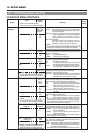
Group
Item
Setting
Contents
Factory
Value
Setting
Upper row: Viewfinder display
Lower row: Counter display indication
AUDIO
VCR SETUP MENU CONTENTS
SERVO
/SYSTEM
12-1 VCR Setup Menu (Cont'd)
LOCAL
FRAME
BLINK
050:
REMOTE SELECT
rnSL
052:
STEP SLOW MODE
StEP
082:
BACK TALLY MODE
rtMd
LOCAL
IEEE1394
IEEE1394+
RS232C
Lc
IE
23
FIELD
FRAME
Fd
FM
OFF
ON
BLINK
oF
on
bL
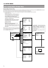
Selection of the method for remote control of the VCR.
LOCAL : Choose this setting when the VCR should
be controlled using the operation buttons on
the GY-DV550 only.
IEEE1394
:
Choose this setting when the VCR should be
remote controlled from a DV connector equipped
video component connected to the DV
connector on the rear section of the GY-DV550.
IEEE1394+RS232C :
Choose this setting for control by means of
the VCR remote control signal from the
REMOTE connector on the GY-DV550.
Note:
•
The operation buttons on the GY-DV550 remain effective
even when set to IEEE1394 or IEEE1394+RS232C.
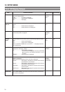
Selects the advance amount in STILL mode.
(Frame/Field advance is effective only with the external
remote control signal.)
FIELD : Field-by-field advance.
FRAME : Frame-by-frame advance.
Selection of the lighting pattern of the BACK TALLY lamp
on the rear section during recording.
OFF : The lamp is always off.
ON :
The lamp lights during recording. It remains off until
the VTR trigger button is pressed to start the recording.
BLINK :
The lamp lights during recording. It blinks when the
VTR trigger button is pressed to start the recording.
OFF
48K
ENABLE
-20dB
244: LOW CUT
LctF
245: SAMPLING RATE
snPL
246: CH1 FRONT VR
ENABLE
FruL
257: AUDIO REF.
SIGNAL LEV
ArEF
VIDEO
126: INPUT SELECT
vid
CAMERA
IEEE1394
cA, iE
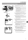
Selection of the input video signal.
Settings cannot be changed during recording.
CAMERA : Camera image is input.
IEEE1394 : The image from the DV connector equipped
video component connected to the DV
connector on the rear section is input.
CAMERA
The setting of this item can only be changed in
the stop mode or when a cassette is not loaded.
Note:
The setting of this item can only be changed in
the stop mode or when a cassette is not loaded.
Note:
When No. 126 INPUT SELECT is set to
IEEE1394, this item cannot be changed.
Note: