


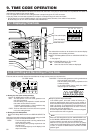
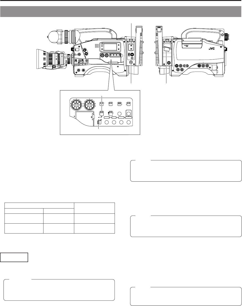
7. SHOOTING OPERATION
58
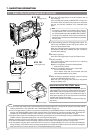
1.
Selecting the power source
Set the POWER switch to DC IN/BATT.
2.
Selecting the device connected to the VTR/RM multi-pin
connector
To connect the external VCR, set the MODE switch to VTR.
With this unit, camera images can be recorded on an external
VCR connected to the VTR/RM multi-pin connector.
There are 2 types of external VCR recording: parallel recording
where recording is performed on both the unit and external
VCR and independent recording where recording is performed
only on the external VCR.
When recording on an external VCR, perform the following
connection and settings.
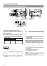
Ⅲ Connect the external VCR to the VTR/RM multi-pin
connector. See the following table for compatible VCRs and
connecting cables.
For the connection of other VCRs, contact your nearest JVC
dealer.
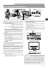
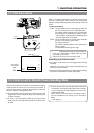
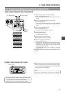
7-6 Recording with an External VCR
Connecting VCR
Connecting cable
Model Connector
S-VHS 14-pin VC-P482 (2m)
BR-S405 VC-P484 (4m)
D9 26-pin VC-P454B (4m)
BR-D40+SA-S40
It is not possible to supply power to the main unit from
an external VCR through the VTR/RM multi-pin
connector.
CAUTION:
Settings
3.
Set the VTR INPUT switch to CAM.
4.
Select the recording VCR using the VTR SELECT switch.
• For parallel recording (this unit and external VCR), set
the switch to PARA.
• To record only with the external VCR, set the switch to
EXT.
5.
The output video signals from the VTR/RM multi-pin
connector can be selected in 26 PIN OUT item on the
Camera SETUP menu screen.
Other than composite signals, another type of video signals
can be selected.
(Y/C, RGB, and component video signals)
☞ See “26 PIN OUT” on page 83.
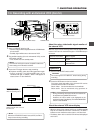
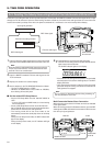
PUSH
PROMPTER
OUTPUT
VTR/RM
CH-1 CH-2
Y/C OUT
TC IN TC OUT
REMOTE
GENLOCK/AUX IN
DV CAMCORDER
GY-DV550
VIDEO OUT
AUDIO IN
FRONT
LENS
MONITOR OUT
LINE OUT
SHUTTERSTATUS
MENU
FILTER
3200k
1
5600k+1/8ND
2
5600k+1/64ND
3
ALARM
MONITOR
OPERATE
NG
GAIN
OUTPUT
WHT.BAL
VTR
ON OFF
AUTO IRIS
LOLUX
BACK L
NORMAL
SPOT L
STRETCH
NORMAL
COMPRESS
LIGHT
ON
OFF
COUNTER
AUDIO SELECT
MANUAL
AUTO
CH-1 CH-2 CH-1 CH-2
REAR
FRONT
RM
AUDIO INPUT
MODE
CTL
TC
UB
CH-1
MIX
CH-2
RESET
OPERATE/WARNING
MONITOR
SELECT
CH-1
AUDIO
LEVEL
CH-2
VTR
ON
OFF
INCOM
MIC
INCOM
MIC
LEVEL
POWER
OFFRM
DC IN
/BATT.
CALL
CARBON
DYNAMIC
FULL AUTO BLACK
AUDIO SELECT
CONTINUE
MANUAL
AUTO
INT
EXT
AUX
GROUP ITEM SELECT DATA SET
HOLD SHIFT ADVANCE PRESET
CAM
CH-1 CH-2 CH-1 CH-2
REAR
FRONT
AUDIO INPUT
CH-1
SEE
INSTR-
UCTION
MANUAL
CH-2
AUDIO
LEVEL
VTR SELECT
VTR INPUT
PARA
REC
FREE
PRST
REGEN
TC GENE.
MENU
LITHIUM BATT.
Memo:
External video signals will not be outputted to the VTR/
RM connector (26-pin) even when setting the VTR
INPUT switch to AUX.
Memo:
VTR SELECT information is displayed in status screen
1 of the viewfinder according to the VTR SELECT switch
setting (PARA or EXT display).
Memo:
Only CH1 audio signal will be outputted from VTR/RM
multi-pin connector for the audio signal.
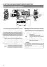
4.
VTR SELECT switch
3.
VTR INPUT switch
1.
POWER switch
VTR/RM multi-pin
connector
2.
MODE switch