


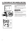
13. FEATURES OF THE CAMERA SECTION
94
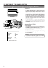
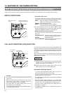
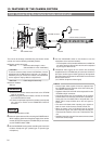
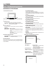
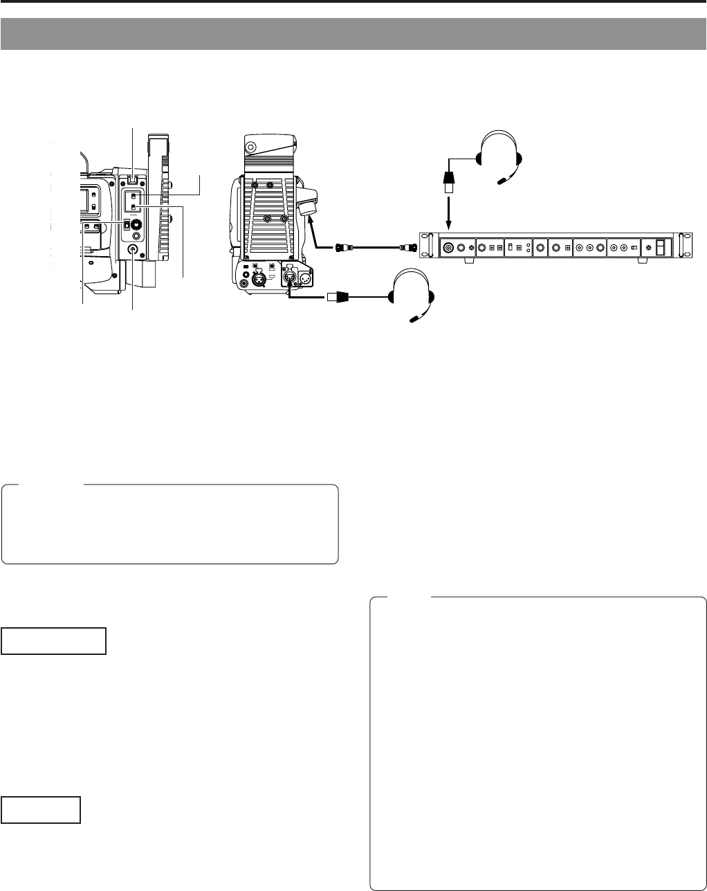
● Connect the camera remote control unit to the VTR/RM
multi-pin connector.
● When using the intercom headset, connect the headset
to the INTERCOM connector.
● To check the prompter output of the camera remote control
unit, connect a monitor to the PROMPTER OUTPUT
connector.
1.
Set the MODE switch to RM.
2.
Select the power source of this unit using the POWER switch.
When supplying power from the power supply of the camera
remote control unit through the VTR/RM multi-pin connector,
set the POWER switch to RM.
3.
Set the INCOM MIC setting switch according to the intercom
headset microphone type (carbon-type or dynamic-type
microphone).
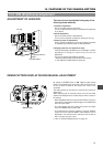
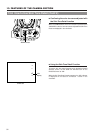
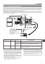
13-8 Connecting the camera remote control unit
Connection
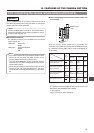
• External input video signals will not be outputted from
the VTR/RM multi-pin connector even when setting the
VTR INPUT switch to AUX.
• Playback video of the VCR will not be outputted from the
VTR/RM multi-pin connector.
• Call signals will be sent to the operator of the camera
remote control unit while the CALL button is held down.
During this time, the BACK TALLY lamp will blink. The
BACK TALLY lamp will blink when the call signal is
received.
• The screen will distort when inputting sync signals to
both the main unit and camera remote control unit.
• When the power is set to ON during input of external
synchronous signals, the screen may shift vertically for
a few seconds; however, this is not a malfunction of the
unit.
• Read the instruction manual of the camera remote control
unit for the correct usage.
Memo:
The unit can be remotely controlled using the camera remote
control unit. Use the following available products.
Ⅲ Camera remote control unit
• RM-P200
...............
Maximum cable length is 100m.
(Not available for 4-inch viewfinders.)
• RM-P300
...............
Cable length is 200m only.
Ⅲ Intercom headset
• KA-310
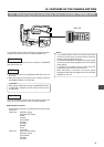
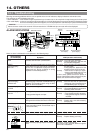
Settings
LIGHT
ON
OFF
COUNTER
AUDIO SELECT
MANUAL
AUTO
CH-1 CH-2 CH-1 CH-2
REAR
FRONT
RM
AUDIO INPUT
MODE
CTL
TC
UB
A
TE/WARNING
O
E
L
CH-2
VTR
ON
OFF
INCOM
MIC
INCOM
MIC
LEVEL
POWER
OFFRM
DC IN
/BATT.
CALL
CARBON
DYNAMIC
INTERCOM
DC INPUT
DV
AUDIO IN
EARPHONE
DC
OUTPUT
LINE MIC
+48V
ON ON
LINE MIC
+48V
REAR
FRONT
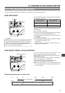
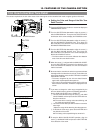
4.
Use the INCOM MIC switch to set whether to use the
microphone of the intercom headset.
• The microphone of the headset will become available for
use when setting to ON and the volume can be adjusted
by turning the volume knob.
5.
Composite video signals of the camera are constantly
outputted from the VTR/RM multi-pin connector. Other than
this signal, another type of video signals can be outputted.
The output signal is selected in 26 PIN OUT of the Camera
SETUP menu screen.
(Y/C, RGB or component video signal)
2.
POWER switch
INTERCOM
connector
BACK TALLY lamp
VTR/RM connector
Camera remote control unit
Headset
3.
INCOM MIC
switch
4.
INCOM MIC
switch
1.
MODE
switch
Headset
To use the camera remote control unit RM-P200, internal
adjustments of the RM-P200 are required. It is, therefore,
mandatory that you contact the nearest JVC-authorized
service agent for inquiry about the adjustments.
CAUTION: