


3. BASIC SYSTEM CONNECTIONS AND ADJUSTMENTS
35
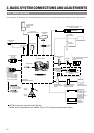
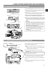
PUSH
PROMPTER
OUTPUT
VTR/RM
CH-1 CH-2
Y/C OUT
TC IN TC OUT
REMOTE
GENLOCK/AUX IN
DV CAMCORDER
GY-DV550
VIDEO OUT
AUDIO IN
FRONT
LENS
MONITOR OUT
LINE OUT
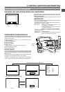
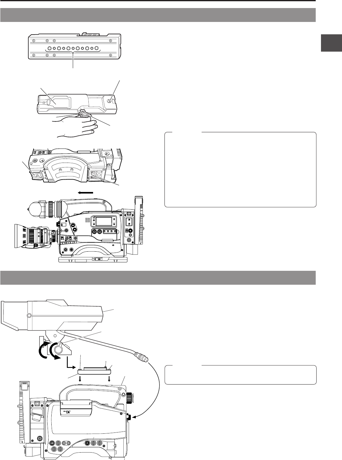
CAUTION:
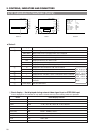
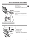
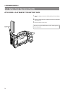
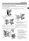
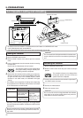
3-6 Attaching the Tripod Base (provided)
Use the provided tripod base to place the camera on a tripod.
1.
Attach the tripod base on the tripod by using the hole that
balances the unit most optimally.
2.
While pushing the safety lever, pull the lock lever toward
the front until the front mount clip clicks into place.
3.
Place the unit on the tripod base by aligning the rear base
mount of the unit with the pin on the tripod base.
4.
Push the unit from the upward direction and slide it toward
the front so that the front base mount of the unit is locked
by the front mount clip of the tripod base as it clicks into
place.
• The front base mount may be locked while the pin of the
tripod base is not inserted into the hole on the rear base
mount of the unit. Therefore, after mounting, make sure
that these parts are engaged properly.
• When moving the unit mounted on a tripod, any impact
or vibration should be avoided as this may cause the unit
to become detached and to drop from the tripod.
Be sure to remove the unit from the tripod before
transporting it.
• The tripod base (KA-510) cannot be mounted.
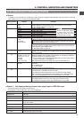
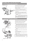
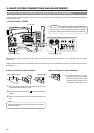
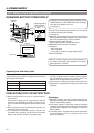
3-7 Attaching the 4-inch Viewfinder (Optional)
CAUTION:
Use the optional viewfinder holder (KA-A40) to mount the 4-
inch viewfinder (VF-P400) on the unit.
1.
Mount the viewfinder holder on the handle section of the
unit.
* Mount it so that the stopper pin of the viewfinder holder
comes to face the front of the unit.
2.
Fix the viewfinder holder securely using two screws.
Unless the screws are securely fixed, the viewfinder may
drop. Exercise maximum caution.
3.
Loosen the lock lever of the 4-inch viewfinder, and slide the
viewfinder forward along the viewfinder holder guide.
4.
Turn clockwise the lock lever of the 4-inch viewfinder and
fix it.
5.
Connect the viewfinder cable connector to the viewfinder
connector of the unit.
VF-P400
Lock lever
handle
stopper pin
mount screw
KA-A40
mount screw
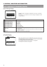
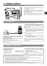
4.
SHUTTERSTATUS
MENU
FILTER
3200k
1
5600k+1/8ND
2
5600k+1/64ND
3
ALARM
MONITOR
OPERATE
NG
GAIN
OUTPUT
WHT.BAL
VTR
ON OFF
AUTO IRIS
LOLUX
BACK L
NORMAL
SPOT L
STRETCH
NORMAL
COMPRESS
LIGHT
ON
OFF
COUNTER
AUDIO SELECT
MANUAL
AUTO
CH-1 CH-2 CH-1 CH-2
REAR
FRONT
RM
AUDIO INPUT
MODE
CTL
TC
UB
CH-1
MIX
CH-2
RESET
OPERATE/WARNING
MONITOR
SELECT
CH-1
AUDIO
LEVEL
CH-2
VTR
ON
OFF
INCOM
MIC
INCOM
MIC
LEVEL
POWER
OFFRM
DC IN
/BATT.
CALL
CARBON
DYNAMIC
FULL AUTOBLACK
Front mount clip
Pin
2.
Safety lever
2.
Lock lever
1. Tripod mounting holes
4.
Front
base
mount
3.
Rear base
mount