


5. PREPARATIONS
41
CAUTION:
1.
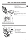
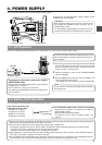
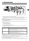
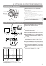
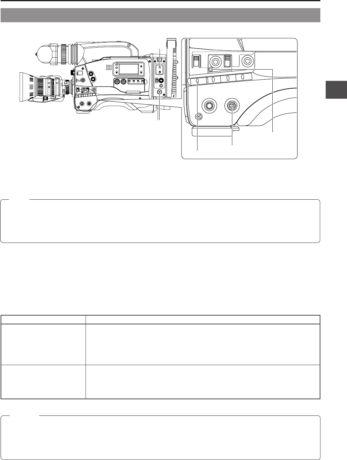
Select the power supplying method to the unit with the POWER switch.
• When supplying power to the unit from the DC IN connector or battery, set the POWER switch to DC IN/BATT.
• When supplying power to the unit from camera control unit through the VTR/RM multi-pin connector, set the switch to RM.
2.
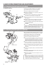
Turn the OPERATE switch to ON.
Ⅲ The power is then supplied to the unit.
• Video image is output to the viewfinder.
• The display of the VCR section is turned on.
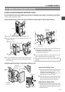
3.
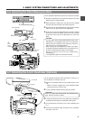
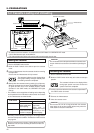
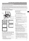
Select the GY-DV550 operation mode with the VTR switch.
• The GY-DV550 operation mode may differ when the power is turned ON and when the cassette is loaded depending on the
setting of the VTR switch as follows:
VTR switch setting
SAVE
STBY
GY-DV550 operation mode
GY-DV550 enters the SAVE mode (tape protect mode) and stops the drum motor. "SAVE" is
displayed in the VCR operation indicating section of the Status 1 mode screen in the viewfinder.
In this mode, the tape is effectively protected.
In this condition, press the VTR trigger button to start recording. However, it takes longer for
the operation to take place from this condition than from the STBY mode.
When a recordable videocassette is loaded, the GY-DV550 enters the record-pause mode
automatically. (The drum motor is still rotating.)
"STBY" is displayed on the Status 1 screen in the viewfinder.
In this condition, pressing the VTR trigger button starts recording immediately.
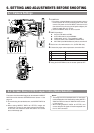
5-1 Turning the Power ON
• Wait at least 5 seconds before turning the OPERATE ON again once it has been turned OFF.
• When the OPERATE is turned OFF, the unit automatically enters the tape protect mode. It takes approximately 5 seconds to
enter the tape protect mode. Do not turn the OPERATE ON again within this interval.
• External VCR will not enter the SAVE mode.
• Do not directly turn the POWER switch to OFF with a tape inserted. (The unit will not enter the tape protect mode.)
SHUTTERSTATUS
MENU
FILTER
3200k
1
5600k+1/8ND
2
5600k+1/64ND
3
ALARM
MONITOR
OPERATE
NG
GAIN
OUTPUT
WHT.BAL
VTR
ON OFF
AUTO IRIS
LOLUX
BACK L
NORMAL
SPOT L
STRETCH
NORMAL
COMPRESS
LIGHT
ON
OFF
COUNTER
AUDIO SELECT
MANUAL
AUTO
CH-1 CH-2 CH-1 CH-2
REAR
FRONT
RM
AUDIO INPUT
MODE
CTL
TC
UB
CH-1
MIX
CH-2
RESET
OPERATE/WARNING
MONITOR
SELECT
CH-1
AUDIO
LEVEL
CH-2
VTR
ON
OFF
INCOM
MIC
INCOM
MIC
LEVEL
POWER
OFFRM
DC IN
/BATT.
CALL
CARBON
DYNAMIC
FULL AUTO BLACK
OPERATE
NG
GAIN
OUTPUT
WHT.BAL
VTR
ON OFF
AUTO IRIS
LOLUX
BACK L
NORMAL
SPOT L
STRETCH
NORMAL
COMPRESS
FULL AUTO BLACK
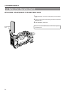
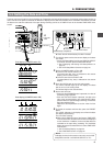
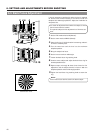
3.
VTR switch
1.
POWER switch
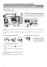
MODE
switch
2.
OPERATE switch
FULL AUTO
lamp
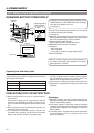
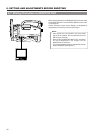
Memo:
It is not possible to supply power to the main unit from an external VCR through the VTR/RM multi-pin connector.
When the POWER switch is set to RM, power supply other than the camera will no turn on during the following conditions. At
this time, the FULL AUTO lamp will flash.
• When the MODE switch is set to VTR.
• When the MODE switch is set to RM and remote control signals are not being received from the camera control unit.