


4. POWER SUPPLY
37
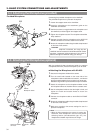
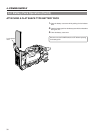
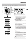
An Anton-Bauer battery pack cannot be connected
directly to the GY-DV550. It is necessary to mount the
optional battery holder.
Battery holder: Anton-Bauer QRQ27
For details on how to mount the battery holder, see
page 39.
*
INTERCOM
DC INPUT
DV
AUDIO IN
EARPHONE
DC
OUTPUT
LINE MIC
+48V
ON ON
LINE MIC
+48V
REAR
FRONT
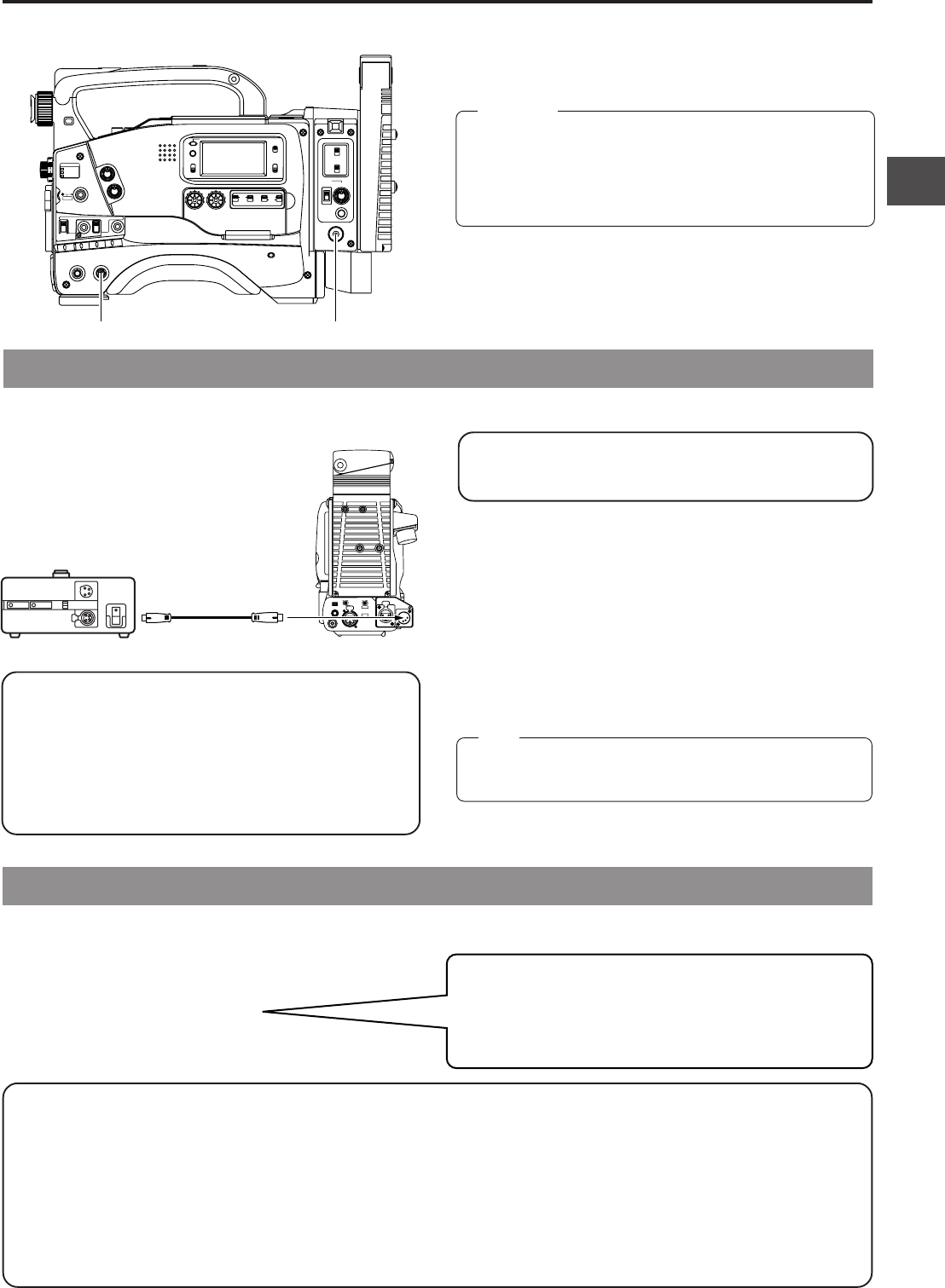
AA-P250
DC cable
AC power adapter
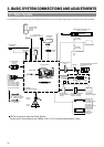
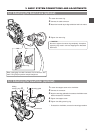
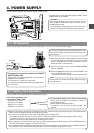
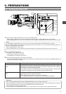
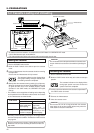
The GY-DV550 is operable with AC power supply or battery pack.
Use the JVC AA-P250 AC power adapter (max. rated output 12.5 V DC, 3.5 A) as the AC power supply.
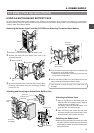
1.
After making sure that the power switches of the GY-DV550
and of the AA-P250 are set to OFF, connect the DC cable
from the AA-P250 to the DC INPUT connector of the GY-
DV550 as shown in the illustration.
2.
When the AA-P250 is used, set the CHARGE/CAMERA
switch to CAMERA.
3.
Set the POWER switch of the main unit to DC IN/BATT, and
set the OPERATE switch to ON.
* For details, read the instruction manual of the AA-P250.
The GY-DV550 can be operated with the following battery packs.
Ⅲ Flat shape type battery pack
Ⅲ Anton-Bauer battery pack
● Propack 13/14 Series
● Trimpack 13/14 Series
● Magnum 13/14 Series
● Compack 13/14 Series
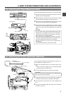
● When the DC cable is connected to the DC INPUT connector, the power supply from the battery pack is interrupted and the
power starts to be supplied through the DC INPUT connector.
● Do not connect or disconnect the DC cable while operating with a battery pack.
The following symptoms may occur if the DC cable is connected or disconnected while operating with a battery pack.
• The power is cut off for a moment when the DC cable is disconnected.
• Noise to the video and audio signals occurs. Audio signal are muted.
● When operation is continued with DC input after the battery pack capacity has been used up, set the OPERATE switch to
OFF after the DC power is applied. Then switch ON again.
● If the GY-DV550 is left with the battery pack attached, a small amount of power is consumed even if the OPERATE switch on
the GY-DV550 is set to OFF. Remove the battery pack when the GY-DV550 is not going to be used.
Do not use any power source with large fluctuations in the
power source voltage, or power sources generating noise,
such as ripples.
4-1 AC Operation
4-2 Battery Pack Operation
Do not remove or connect the DC cable while recording is
being performed.
Note:
Precautions for Connection with the AC POWER
ADAPTER(AA-P250)
Always use the DC cable equipped with a ferrite core and
supplied with the AA-P250.
The DC cable VC-710(5m) can not be used.
If the cable is not equipped with a ferrite core, please contact
your JVC dealer.
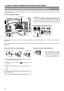
To operate the unit using AC power supply or battery, set the
POWER switch to DC IN/BATT.
When supplying power to the unit from cameral control
unit through the VTR/RM multi-pin connector, set the
POWER switch to RM.
It is not possible to supply power to the main unit from an
external VCR through the VTR/RM multi-pin connector.
CAUTION:
STATUSSHUTTER
MENU
FILTER
3200k
1
5600k+1/8ND
2
5600k+1/64ND
3
ALARM
MONITOR
OPERATE
NG
GAIN
OUTPUT
WHT.BAL
VTR
ON OFF
AUTO IRIS
LOLUX
BACK L
NORMAL
SPOT L
STRETCH
NORMAL
COMPRESS
LIGHT
ON
OFF
COUNTER
AUDIO SELECT
MANUAL
AUTO
CH-1 CH-2 CH-1 CH-2
REAR
FRONT
RM
AUDIO INPUT
MODE
CTL
TC
UB
CH-1
MIX
CH-2
RESET
OPERATE/WARNING
MONITOR
SELECT
CH-1
AUDIO
LEVEL
CH-2
VTR
ON
OFF
INCOM
MIC
INCOM
MIC
LEVEL
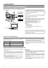
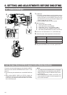
POWER
OFFRM
DC IN
/BATT.
CALL
CARBON
DYNAMIC
FULL AUTO BLACK
POWER switchOPERATE switch