


24
2. CONTROLS, INDICATORS AND CONNECTORS
MENU
OVER
OVER
LIGHT
ON
OFF
COUNTER
CTL
TC
UB
RESET
OPERATE/WARNING
MONITOR
SELECT
E
REV FWD
FBATT
H
HM
MSF
REMAIN
AUD LOCK
32k
CH 1
CH 2
48k
PB NDF
AUTO OFF DEW
L iRFSERVO
HOLD
SP
40 30 20 10 0
dB
CH-1
MIX
CH-2
WIDE
SLAVE
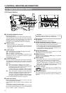
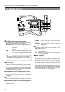
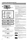
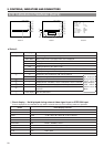
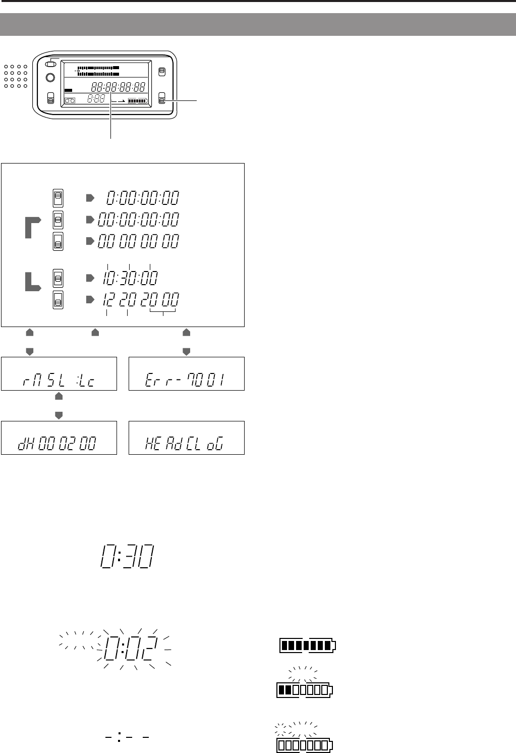
The counter display shows the following 4 types of information.
1.
Tape counter display
The counter display usually functions as a tape counter
(hour, minute, second, frame). It can be switched to a CTL
counter, time code or user's bit display by using the
COUNTER switch. (When the VCR Setup Menu item No.
516 DISPLAY SELECT is set to “TC”.)
• CTL counter: Time between -9 hr. 59 min. 59 sec. 29
frames and 9 hr. 59 min. 59 sec. 29 frames
can be displayed.
* CTL counter indication may also corrupt
at playback of segment which time code
signal is not continuously recorded.
• Time code : Time between 0 hour and 23 hr. 59 min. 59
sec. 29 frames can be displayed.
• User's bit : Hexadecimal number from 0 to F is displayed
in 8 digits.
When the VCR Setup Menu item No. 516 DISPLAY SELECT
is set to “CLOCK”, the date and time are displayed. Set the
COUNTER switch to TC or UB.
TC: Time (Hour, Min., Sec.) is displayed.
UB: Date (Month, Day, Year) is displayed.
• Press the MENU button to switch to the VCR Setup Menu
setting display.
2.
VCR Setup Menu setting display
This display is used when setting the setup menus. After
setting of the setup menus, the tape counter display returns.
For details, see "DISPLAYING AND SETTING VCR SETUP
MENUS" on page 73.
3.
Hour meter display
The hour meter is displayed by selecting the HM group from
the VCR Setup Menu.
The hour meter data refers to the accumulated head drum
running time.
4.
Error code/Alarm display
The error code or alarm indicator is displayed automatically
in case an abnormal condition occurs with the unit.
☞ See “TROUBLES WITH ERROR CODE OUTPUTS” on
page 100.
☞ See “ALARM INDICATIONS” on page 96.
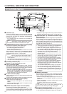
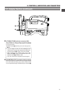
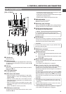
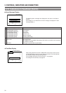
Remaining Battery Power Display
The 7-dot segment bar display shows the remaining battery
power. The lighted segment bars decrease as the remaining
battery power decreases.
• To display the remaining battery power accurately, set the
VCR Setup Menu item No. 396 BATTERY TYPE according
to the type of the battery pack in use.
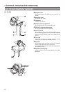
All segment bars light when a fully charged
battery pack is attached.
The last 2 segment bars and "BATT" start
to blink when the battery is nearly
exhausted. Replace with a fully charged
battery pack.
When the battery capacity has run out, "E"
and "BATT" blink and the unit stops
operation automatically.
EFBATT
E BATT
E BATT
HM
REMAIN
HM
REMAIN
HM
REMAIN
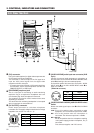
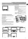
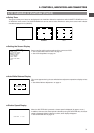
Remaining Tape Time Display
This display shows the remaining tape time (minutes/seconds)
in record and play modes.
• Example: 30 minutes of remaining tape.
• This indicator blinks when remaining tape time is equivalent
to less than 2 minutes.
* An alarm sounds as a warning when remaining tape time is
equivalent to less than 2 minutes in the record mode
• The following display appears when no videocassette is
loaded or during the calculation of remaining tape that takes
place immediately after a videocassette is inserted.
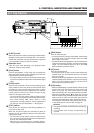
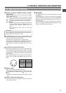
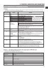
2-7 Counter Display Contents
COUNTER
switch
Counter display
2. 4.
H
3.
H M S F
1.
CTL
TC
UB
H M S F
CTL
TC
UB
CTL
TC
UB
H M S
CTL
TC
UB
CTL
TC
“CTL”
“TC”
“UB”
“TC”
“UB”
UB
4.
CTL counter
Time code
User’s bit
Time display
Date display
Hour Min Sec
Month Day Year
“TC”
VCR Setup
Menu No. 516
DISPLAY SELECT
“CLOCK”
VCR Setup Menu display Error code display
Hour meter display Alarm display
Tape counter display