


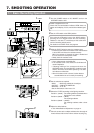
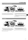
7. SHOOTING OPERATION
57
M: 909
STBY
INT
4V21.<60
CH1 - ----+--
CH2-----+--
AUX
M: 909
4V21.
AUX
PUSH
PROMPTER
OUTPUT
VTR/RM
CH-1 CH-2
Y/C OUT
TC IN TC OUT
REMOTE
GENLOCK/AUX IN
DV CAMCORDER
GY-DV550
VIDEO OUT
AUDIO IN
FRONT
LENS
MONITOR OUT
LINE OUT
SHUTTERSTATUS
MENU
FILTER
3200k
1
5600k+1/8ND
2
5600k+1/64ND
3
ALARM
MONITOR
OPERATE
NG
GAIN
OU
TPUT
W
HT.BAL
VTR
ON OFF
AUTO IRIS
LOLUX
BACK L
NORMAL
SPOT L
STRETCH
NORMAL
COMPRESS
LIGHT
ON
OFF
COUNTER
AUDIO SELECT
MANUAL
AUTO
CH-1 CH-2 CH-1 CH-2
REAR
FRONT
RM
AUDIO INPUT
MODE
CTL
TC
UB
CH-1
MIX
CH-2
RESET
OPERATE/WARNING
MONITOR
SELECT
CH-1
AUDIO
LEVEL
CH-2
VTR
ON
OFF
INCOM
MIC
INCOM
MIC
LEVEL
POWER
OFFRM
DC IN
/BATT.
CALL
CARBON
DYNAMIC
FULL AUTO BLACK
AUDIO SELECT
CONTINUE
MANUAL
AUTO
INT
EXT
AUX
GROUP ITEM SELECT DATA SET
HOLD SHIFT ADVANCE PRESET
CAM
CH-1 CH-2 CH-1 CH-2
REAR
FRONT
AUDIO INPUT
CH-1
SEE
INSTR-
UCTION
MANUAL
CH-2
AUDIO
LEVEL
VTR SELECT
VTR INPUT
PARA
REC
FREE
PRST
REGEN
TC GENE.
MENU
LITHIUM BATT.
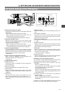
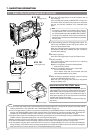
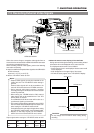
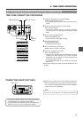
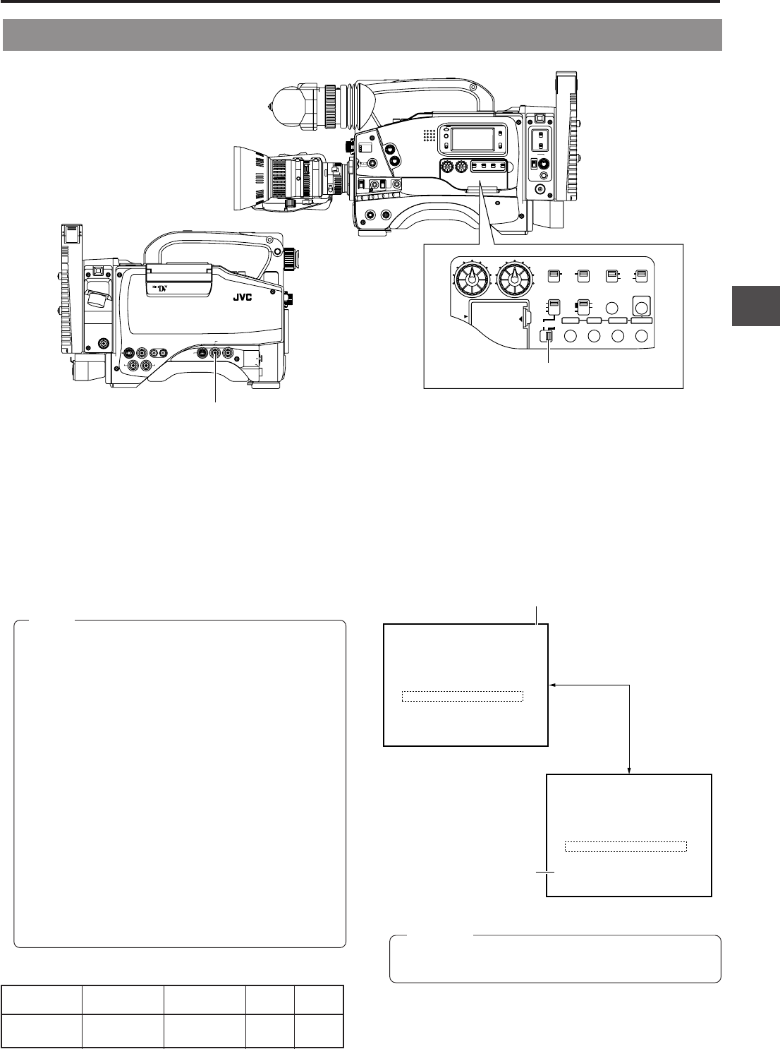
7-5 Recording External Video Signals
Other than camera images, composite video signals from an
external device connected to the GENLOCK/AUX IN connector
can also be recorded with this unit.
When recording external video signals, perform the following
connection and setting.
Ⅲ Input the stabilized composite video signals to the GENLOCK/
AUX IN connector.
Input level: 1V (P-P) ±0.3V (P-P)
Ⅲ Set the VTR INPUT switch to AUX.
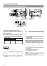
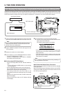
Memo:
• External video signals can only be recorded on the
VCR of this unit. The VTR SELECT switch setting is
ignored.
External video signals will not be recorded on the
external VCR connected to the VTR/RM connector.
• During external video signal recording, recording
check by pressing the RET button on the lens section
cannot be performed.
• When setting the VTR/RM switch to RM, external
video signals will not be recorded even if the VTR
INPUT switch is set AUX.
The GENLOCK/AUX IN connector will function as a
synchronous signal input connector.
• The camera images will be outputted from the VIDEO
OUT connector and VTR/RM multi-pin connector even
when setting the VTR INPUT switch to AUX.
For details concerning the output images when setting
the VTR INPUT switch to AUX, see the following table.
• Whether to add setup signals can be selected in
SETUP item of the Camera SETUP menu screen.
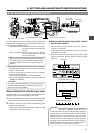
Viewfinder MONITOR Y/C OUT VIDEO VTR/RM
OUT OUT (26-pin)
AUX (external) AUX (external) AUX (external) Camera Camera
video video video images images
Output signals when setting the VTR INPUT switch to AUX
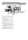
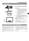
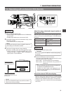
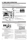
Ⅲ About the status screen display of the viewfinder
During external video signal recording, camera setting related
information will not be displayed on the status screens.
The displayed status screens are as follows:
• Status screens 0 and 1 are displayed. Status screen 2 will
not be displayed.
• AUX will appear on the upper right of the screen.
• INT will constantly appear in the VTR SELECT display.
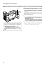
Do not change the VTR INPUT switch setting during
recording.
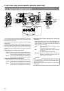
CAUTION:
STATUS button
GENLOCK/AUX IN
VTR INPUT switch
AUX indicator
Status screen 0
INT indicator
Status screen 1