


11. USING EXTERNAL COMPONENTS
70
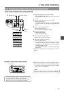
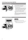
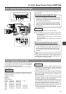
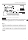
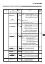
11-1 Connecting a Video Component with DV Connector
INTERCOM
DC INPUT
DV
AUDIO IN
EARPHONE
DC
OUTPUT
LINE MIC
+48V
ON ON
LINE MIC
+48V
REAR
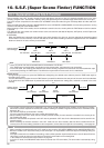
FRONT
Rear section of GY-DV550
DV connector
DV cable
DV connector
Video component with DV Connector
When connecting the GY-DV550 to other component with DV connector, be sure to observe the following procedure.
Ⅲ When using the GY-DV550 as playback component
1.
Turn ON both units.
2.
Confirm that the VCR Setup Menu item No.126 INPUT
SELECT is set to “CAMERA”(cA).
* If set to “IEEE1394”, set it to “CAMERA” and then turn
ON the power again.
3.
Insert the videocassette.
4.
Connect the DV cable.
* Always connect the DV cable last.
Ⅲ When using the GY-DV550 as recording component
1.
Turn ON both units.
2.
Set VCR Setup menu No. 257 AUDIO REF. SIGNAL LEV.
For proper E-E audio output, set the VCR Setup Menu No.
257 to the audio reference level of the tape on the player (-
12 dB or -20 dB).
3.
Set the VCR Setup Menu item No.126 INPUT SELECT to
“IEEE1394”(iE).
4.
Insert the videocassette.
5.
Connect the DV cable.
* Always connect the DV cable last.
• When recording while controlling the GY-DV550
through the DV connector from another component
with DV connector, set the VCR Setup Menu item
No.050 REMOTE SELECT to “IEEE1394”.
In this case, it takes approximately 2 to 3 seconds
before recording starts on the GY-DV550.
• The audio recording level to the tape constitutes an
input signal reference level regardless of setting the
VCR Setup Menu No. 257 AUDIO REF. SIGNAL LEV.
• When the GY-DV550 is controlled through the DV
connector, set the VCR Setup Menu item No.050
REMOTE SELECT to “IEEE1394”.
However, the following functions may not work
depending on the component that the GY-DV550 is
connected to.
REC
FF (FWD search is possible)
REW (REV search is possible)
• When the DV cable is connected for communication
with another component, to stabilize the IEEE1394
output signal, the STILL mode is activated for a few
seconds and the LED of the STILL button on the top
section of the GY-DV550 lights when the mode is
switched to PLAY or x1 FWD search.
∗ The x1 FWD search only works during IEEE1394
control or RS-232C control.
• The operation method differs with the characteristics
and specifications of the connected equipment. Even
if connection is possible, operation or data
communication may sometimes be impossible to
perform.
Memo:
If the above procedure is not performed correctly, the playback picture may be disturbed or the sound may fall out. If this
happens, redo the connection by performing steps
1.
to
4.
described above.
Note:
Memo:
When VCR Setup menu No. 126 INPUT SELECT is set
to IEEE1394, No. 257 AUDIO REF. SIGNAL LEV setting
cannot be changed.
Memo:
Ⅲ When the GY-DV550 is used as camera, and a backup
recording is made on another component via the DV
connector, set the VCR Setup Menu item No.126 INPUT
SELECT to “CAMERA”.