


27
2. CONTROLS, INDICATORS AND CONNECTORS
STATUSSHUTTER
MENU
FILTER
3200k
1
5600k+1/8ND
2
5600k+1/64ND
3
ALARM
MONITOR
OPERATE
NG
GAIN
OUTPUT
WHT.BAL
VTR
ON OFF
AUTO IRIS
LOLUX
BACK L
NORMAL
SPOT L
STRETCH
NORMAL
COMPRESS
LIGHT
ON
OFF
COUNTER
AUDIO SELECT
MANUAL
AUTO
CH-1 CH-2 CH-1 CH-2
REAR
FRONT
RM
AUDIO INPUT
MODE
CTL
TC
UB
CH-1
MIX
CH-2
RESET
OPERATE/WARNING
MONITOR
SELECT
CH-1
AUDIO
LEVEL
CH-2
VTR
ON
OFF
INCOM
MIC
INCOM
MIC
LEVEL
POWER
OFFRM
DC IN
/BATT.
CALL
CARBON
DYNAMIC
FULL AUTO BLACK
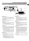
STATUS
button
BATT ALARM
REC
BATT
Lamp
REC/ALARM
Lamp
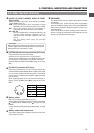
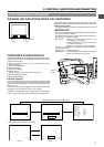
The viewfinder has two LED indicators below the screen. These LEDs
light or blink to indicate the present status of the camera or the VCR.
●
[BATT] battery lamp
This lights red when the battery voltage becomes too low for
operating the camera.
●
REC/ALARM lamp
The internal VCR status is displayed when the VTR SELECT
switch is set to INT or PARA.
This lights or blinks green under the following circumstances.
Steady green : During recording.
Blinks green : • While the GY-DV550 switches from
record-pause to recording.
• Immediately before the tape is running out
or when it has run out.
• When an error occurs in the GY-DV550.
The external VCR status is displayed when VTR SELECT
switch is set to EXT.
Steady green : During recording.
Blinks green : • Immediately before the tape is running out.
• When an error occurs in the VCR.
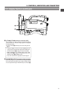
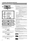
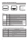
2-10 Indications in Viewfinder
VIEWFINDER SCREEN DISPLAY
The following indications are displayed on the viewfinder screen.
(However, this information is not displayed while the VCR section
is playing back a tape.)
Ⅲ Status screens (screens for use in checking the current
camera settings)
Ⅲ Alarm message display
Ⅲ Time date display
Ⅲ Safety zone display
Ⅲ Setting screen
(screen for use in the camera and VCR setup)
Ⅲ Auto white balance display
Ⅲ Shutter speed display
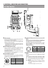
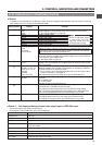
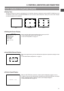
Ⅲ Status Screens
Press the STATUS button during normal screen display to show
one of the status screens in the viewfinder. One of the three
status screens will be displayed every time the button is pressed.
(Status 0, 1, 2)
The status 2 screen will not appear during external video signal
input (when the VTR INPUT switch is set to AUX).
In addition, AUX will appear on the upper right of status screen
0 and 1 and camera setting related display will not be made.
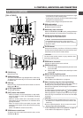
WARNING LED INDICATORS INSIDE THE VIEWFINDER
ACCU- FOCUS
G
F
I
SD
B
ACCU
M: 909
-FOCUS
G
F
I
F5.6
STBY
REC2
EXT
4V21.<60
B
CH1 - ----+--
CH2-----+--
WH I T E BA L A
SCENE F I LE A
FILTER
3.2K
SHUTTER 1/1000
GA IN 6dB
IRIS LEVEL NORMAL
I R I S DETECT NORMAL
FULL AUTO OFF
REC T IME <60
SD
M: 909
Status 0 Status 1 Status 2
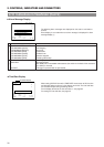
• VTR INPUT switch: During CAM setting
Status 0 Status 1
AUX AUX
M: 909
STBY
INT
4V21.<60
CH1 - ----+--
CH2-----+--
M: 909
• VTR INPUT switch: During AUX setting