


14
Introduction
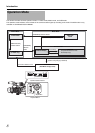
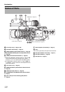
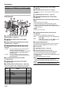
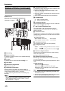
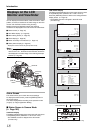
Side Terminal
A [Y/VIDEO] Y/Composite Video Signal Output
Terminal (BNC) (A Page 122)
B
[PB] PB Video Signal Output Terminal (BNC)
(
A
Page 122)
C [GENLOCK/AUX] Genlock/AUX Selection Switch
(U model only) (A Page 125)
D
[GENLOCK/AUX IN] Genlock/AUX Input Terminal
(U model)/[GENLOCK INPUT] Genlock Input Terminal
(E model)
U model : For input of external synchronizing signals or
external composite video signals.
(A Page 125 [Input of Composite Video Signals
from External Device (GY-HM790CHU/GY-
HM790U only)])
E model : For input of external synchronizing signals.
(A Page 126 [Input of External Synchronizing
Signal (Genlock)])
E [TC IN] Time Code Input Terminal (BNC)
( A Page 48 to 52)
F [TC OUT] Time Code Output Terminal (BNC)
( A Page 48 to 52)
G [STUDIO] Studio Terminal (10-pin) (A Page 128)
Connect to this terminal when combining the use of products,
such as a transmission unit, from a different manufacturer.
H
[PR] PR Video Signal Output Terminal (BNC)
(
A
Page 122)
I
[DC INPUT] DC Input Terminal (
A
Page 22)
Input terminal for DC 12 V power supply. Connects with an
AC adapter.
J
[REMOTE] Remote Terminal (
A
Page 131)
K
[HD/SD-SDI] HD/SD-SDI Output Terminal (BNC)
(
A
Page 122)
L
[AUDIO OUTPUT CH-1/CH-2] Audio Output Terminal
(RCA)
Output terminal for audio signals.
●
Input audio signals are output during Camera mode.
●
Playback audio signals are output during Media mode.
●
Audio from input audio signals is output during HD/DV signal
(IEEE1394) input.
Memo :
●
Alarm tone is not output.
M
[INT/EXT] IEEE1394 Interface Terminal Switch
(
A
Page 123)
For selecting a valid IEEE1394 interface terminal.
N
Shoulder Pad Slide Button
For adjusting the shoulder pad position. Press this button to
adjust the shoulder pad O position to the front or back.
O
Shoulder Pad
P
[USB] USB Terminal (
A
Page 130)
Q
[IEEE1394] IEEE1394 Terminal (4-pin)
For connecting digital video equipment with IEEE1394
terminal using an IEEE1394 cable (sold separately).
To enable this terminal, set the [INT/EXT] IEEE1394 terminal
switch M to [EXT].
(A Page 123 [IEEE1394 Connection])
Note :
●
When connecting IEEE1394 cables, check that the
connectors are facing the right direction before you insert.
Memo :
●
Put on the covers when the connectors are not in use.
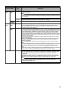
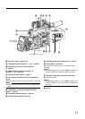
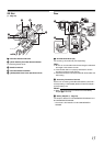
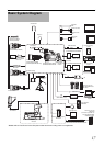
Names of Parts (continued)
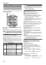
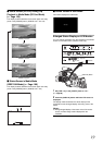
Pin No. Signal
Input/
Output
1NC ^
2 CALL TALLY IN
3 RM TALLY OUT
4 RM PREVIEW OUT
5NC ^
6NC ^
7 TALLY IN IN
8 RETURN GND ^
9 RETURN IN IN
10 GND ^
KL M N O
P
Q
IH
C
A
D
E
F
G
J
B
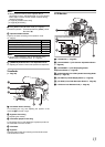
[EXT]
Enables IEEE1394 signals from the [IEEE1394]
terminal Q.
[INT]
Enables the accessory connector B at the rear
of the camera recorder. (A Page 15)