


48
Shooting
Time code and user’s bit data are recorded with the video in
this camera recorder.
The time code and user’s bit are displayed on the viewfinder
and LCD screens during playback or recording.
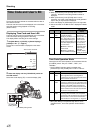
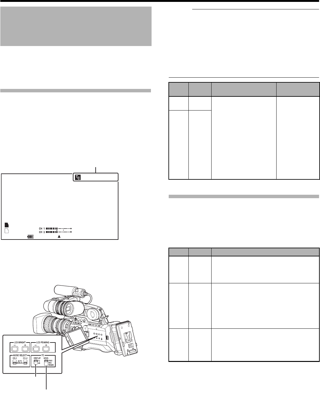
(Status screen)
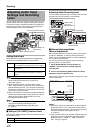
Displaying Time Code and User’s Bit
The time code and user’s bit are displayed on the viewfinder
and LCD screens during playback or recording.
The display differs according to the menu settings.
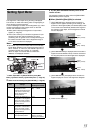
1 Set [Main Menu] B [LCD/VF] B [Status Display] B
[TC/UB] to AOnB. (A Page 91)
Time code or user’s bit data is displayed on the status
screen.
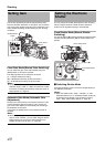
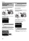
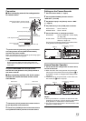
2 Select the display with the [TC DISPLAY] switch on
the LCD monitor.
Select time code display (TC) or user’s bit display (UB).
Memo :
● When [TCG Source] in the [TC/UB] menu is set to
AInternalB, the built-in time code generator number is
displayed.
● When [TCG Source] in the [TC/UB] menu is set to
AExternalB, the value of the external time code generator
input to the [TC IN] terminal is displayed.
● Time code display for [IEEE1394] input is not supported.
● Values recorded on the SDHC card is displayed in Media
mode.
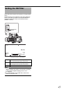
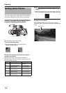
Time Code Operation Mode
Three types of time code operation can be selected with the
[TC GENE.] switch. They are AFREEB, ARECB, and
AREGENB.
* The [TC GENE.] selection switch is enabled when
[TCG Source] in the [TC/UB] menu is set to AInternalB.
* When [Rec Mode] in the [Record Set] menu is set to
AVariable FrameB, time code operation enters RecRun
mode.
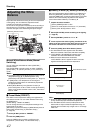
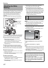
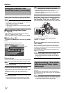
Time Code and User’s Bit
00:00:00:00
MAX 123%
MIN 45%
S.DTL
B -3
ND1/16 A<3200K>
F5.6 AE+1 9dB 1/10000
STBY
100min
100min
1280x720
24p HQ
B
A
282min
30/24 fps
Time Code or User’s Bit
STATUS 1 Screen
[TC DISPLAY]
Setting Switch
[TC GENE.] Setting Switch
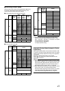
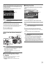
Setting Display LCD/VF Display
VIDEO Output
Display
TC
Time
Code
When [Main Menu] B
[LCD/VF] B [Status
Display] B [TC/UB] is set to
AOnB, time code or user’s
bit is displayed during the
following status display and
information display mode of
the LCD screen.
Ⅵ
STATUS 1 screen in
Camera mode
Ⅵ
STATUS 1, STATUS 2
screens in Media mode (SD)
When [Analog
Out Char.] or
[SDI Out Char.] in
the [A/V Out]
menu is set to
AOnB, time code
or user’s bit is
displayed in the
respective video
output images
during the
LCD/VF display
setting on the left.
UB
User’s Bit
Setting Mode
Description
FREE
FreeRun
mode
The time code operates in the run mode at all
times regardless of the recording status.
It continues to run even when the power of the
camera recorder is turned off. *
REC
RecRun
mode
The time code operates in the run mode during
recording. It continues to run in the order of the
recorded clips as long as the SDHC card is not
replaced. If the SDHC card is removed and
recording is made on another card, time code
will be recorded on the new card from where it
was left off in the previous card.
REGEN
Regen
mode
The time code operates in the run mode during
recording. When the SDHC card is replaced,
the last time code recorded on the card is read
and recorded on a new card so that the time
code continues in running order. (A Page 52)