


53
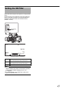
Connection
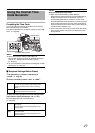
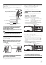
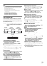
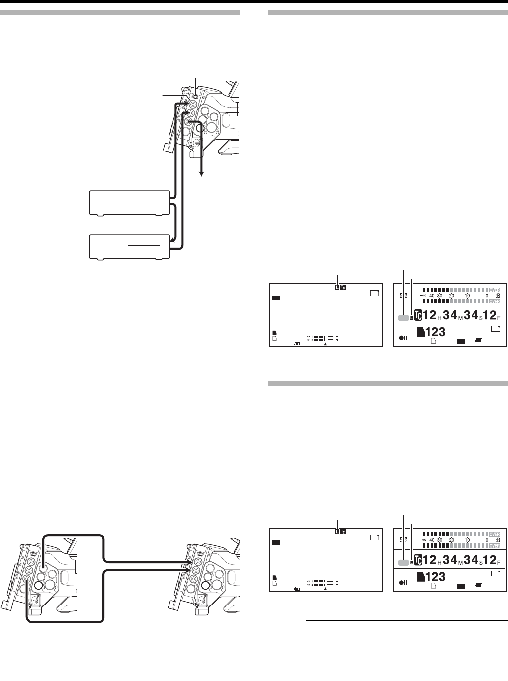
Ⅵ When connecting external time code generator
to a master device
1
Input the external synchronizing signal to the external
time code generator and the [GENLOCK/AUX INPUT]
terminal of this camera recorder.
Make use of BB signal or HDTV 3 level synchronizing signal
as the external synchronizing signal.
Note :
● If the power of the camera recorder is turned ON/OFF
during input of the external synchronizing signal, the
screen may be disrupted for a few seconds. This is not a
malfunction.
2 Input the SMTPE/EBU LTC time code from the
external time code generator to the [TC IN] terminal of
this camera recorder.
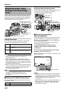
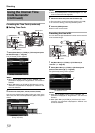
Ⅵ When connecting multiple units of this camera
recorder with one as the master and the rest as
slave devices
1
Connect the [TC OUT] terminal of the master device to
the [TC IN] terminal of the slave device.
2 Connect the [Y/VIDEO] terminal of the master device
to the [GENLOCK INPUT] terminal of the slave device.
Settings on the Camera Recorder
1
Set to the Camera mode. (
A
Page 8)
2 Set the [GENLOCK/AUX] selection switch to
AGENLOCKB. (U model)
3 Set [Genlock Input] in the [Others] menu to ABNCB.
(A Page 93)
4 Set [TCG Source] in the [TC/UB] menu as follows.
● Slave device : Set to AExternalB
● Master device : Set to AInternalB
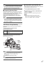
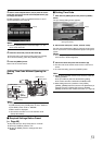
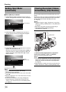
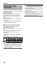
5 Set the LCD monitor or viewfinder as follows.
● Viewfinder : Set to the STATUS 1 screen display
(A Page 108)
● LCD monitor : Set to the enlarged status display
screen (A Page 110)
The input and synchronizing status of the external time
code generator are displayed as follows.
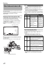
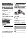
Camera Recorder Operation
1
Set the external time code generator or master device,
and run the time code.
● When the built-in time code generator is synchronized
with the input of the external time code generator, L on
the STATUS 1 screen or enlarged status display screen
will light up.
● If the time code is not synchronized or when there is no
time code input, L does not light up.
Memo :
● After synchronization is complete, the built-in time code
generator will continue to run even when the external time
code generator or master device is disconnected.
● The user’s bit becomes the data of the external time code
generator or master device.
SYNC Signal Generator
External Time Code
Generator
External Synchronizing Signal
[GENLOCK/AUX] Switch
[GENLOCK/AUX INPUT] Terminal (U Model)
[GENLOCK INPUT] Terminal (E Model)
External Synchronizing Signal
Master Device
Slave Device
LTC Time Code
To [TC IN]
terminal of
another camera
[GENLOCK/AUX INPUT] Terminal
Master Device
[TC IN] Terminal
Slave Device
[TC OUT] Terminal
[Y/VIDEO] Output Terminal
00:00:00:00
20 min
MAX 123%
MIN 45%
SKIN AREA
S.DTL
B -3
ND1/16 A<3200K>
F5.6 AE+1 9dB 1/10000
STBY
100min
100min
1280x720
60p HQ
OK
B
A
282min
30/24 fps
DD
DF
EXT
A
B
123 min
min
OK
1280 x 720
60p HQ
CH1
CH2
STBY
100min
67.8min
DD
[TCG Source] : AExternalB
Status Screen
Enlarged Status Display Screen
Lights up
Lights up