16 C1695M-B (11/08)
Connections
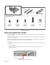
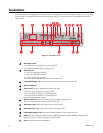
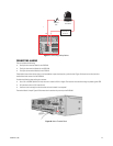
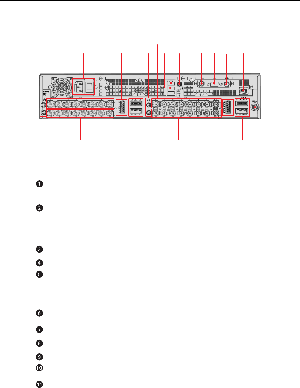
Familiarize yourself with the DVR5100 rear panel before connecting any equipment to the unit. The DVR5100 is available as a 4-, 8-, or 16-analog
input DVR. Figure 11 shows the DVR5116 rear panel for the 16-analog input DVR. The rear panels of the 4- and 8-analog input DVR units are
slightly different.
Figure 11. DVR5100 Rear Panel
Audio Inputs 1 and 2:
• Two audio inputs are provided for a 4- and 8-channel DVR.
• Four audio inputs are provided for a 16-channel DVR.
Video Inputs 1–8:
• 1–8 for a 16-analog camera input DVR.
• 1–8 for an 8-analog camera input DVR.
• 1–4 for a 4-analog camera input DVR
The rear panel layouts might be different for the 4- and 8-channel DVR.
Looping Video Outputs 1–8: One looping video output is provided for each analog camera input.
AC Power Connector
Relays 1 and 2: One relay is provided for every four analog inputs:
• One relay output is provided for a 4-analog input DVR.
• Two relay outputs are provided for an 8-analog input DVR.
• Four relay outputs are provided for a 16-analog input DVR.
Relays are numbered from top to bottom.
Alarms 1–4 and 5–8: One programmable alarm input is provided for each video input.
Alarms are numbered from the upper left through the lower right.
Audio Inputs 3 and 4: Audio inputs 3 and 4 are for channels 9 and 10.
Video Inputs 9–16: Analog camera inputs 9–16 for a 16-analog input DVR.
Looping Video Outputs 9–16: One looping video output is provided for each analog camera input.
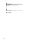
USB 2.0: Two USB 2.0 ports are provided to connect a USB device (such as an optional KBD5000), a standard USB PC
keyboard and mouse, or a USB memory device (for exporting video).
RJ-45: Gigabit Ethernet RJ-45 port (1000Base-T).
ᕦᕧ
ᕩ
ᕡ
ᕣ
ᕢ
ᕥᕤ
ᕨ
ᕫᕾ
ᕫᕵ
ᕫᕶ
ᕫᕷ
ᕫᕸ ᕫᕹ
ᕫᕺ
ᕫᕻ
ᕫᕼ
ᕫᕽ


