22 C1695M-B (11/08)
CONNECTING RELAY DEVICES
Consider the following when wiring the connector:
• Use a 16–26 AWG (0.14 to 1.5 mm
2
) wire that is rated for 250 V or higher. The insulation must be thick enough to protect against
electrostatic discharge (ESD).
• Strip the relay control wire to 0.3 inches (7.6 mm).
• Insert the wire far enough into the connector so that the metal is not exposed.
• Install an external, more powerful relay when you are using a relay with a higher load.
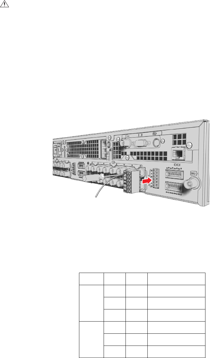
The unit includes one 6-pin relay control terminal block (for the DVR5104 and DVR5108) and two 6-pin relay control terminal blocks (for the
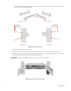
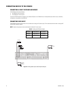
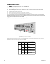
DVR5116). These blocks have tension clamps. Use a small screwdriver to open the clamp for a particular lead. Figure 16 illustrates how to wire
the relay control terminal block and connect it to the DVR5100.
NOTE: The terminal block is keyed and attaches only one way to the DVR5100.
Figure 16. Relay Control Terminal Block
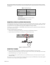
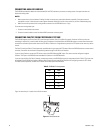
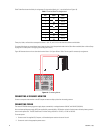
Table E identifies the pin assignments for the relay control terminal blocks. Pin 1 is the top lead on the terminal block. Figure 17 on page 23
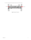
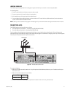
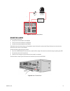
illustrates how to wire the relay with its power source to the DVR5100.
WARNING: Do not exceed the maximum ratings: 30 VDC, 2 A; 125 VAC, 0.5 A.
Table E. Relay Control Terminal Blocks Pin Assignments
Relay Pin Label
Lead
1, 3 1 NO
Normally Open
2C
Common
3NC
Normally Closed
2, 4 4 NO
Normally Open
5C
Common
6NC
Normally Closed


