C1695M-B (11/08) 55
SUPERVISED ALARMS
When an alarm is configured as a supervised alarm, the DVR5100 maintains a constant electrical current through the alarm circuit (5.0 VDC,
10 kohms), including a 10 kohms resistor. If the resistance changes, due to an electrical short or a bypass, the voltage fluctuates from its normal
state. Therefore, the unit triggers an alarm.
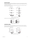
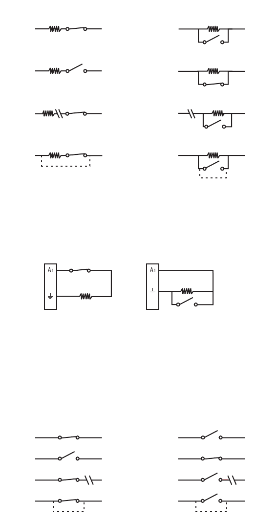
Figure 57 illustrates the alarm and no alarm conditions of a supervised alarm input. Whether the alarm is normally closed or normally open,
neither a cut nor a bypass can defeat these alarms.
Figure 57. Supervised Alarm Conditions
Figure 58 illustrates the wiring configuration for supervised alarm inputs.
Figure 58. Supervised Alarm Input Wiring
UNSUPERVISED ALARMS
When an alarm is configured as unsupervised, the DVR5100 triggers an alarm only when the normal alarm state (open or closed) changes.
Figure 59 illustrates the alarm and no alarm conditions of an unsupervised alarm input. A normally closed alarm input can be defeated with a
bypass; a normally open input can be defeated with a cut.
Figure 59. Unsupervised Alarm Conditions
NORMALLY OPEN
NORMALLY CLOSED
ALARM
GND
+V
+V
ALARM
GND
+V
+V
ALARM
GND
CUT
NO ALARM
GND
ALARM
GND
+V
+V
+V
+V
ALARM
GND
BYPASS
CUT
BYPASS
NO ALARM
GND
ALARM
GND
10 K
Ω
10 K
Ω
10 K
Ω
10 K
Ω
10 K
Ω
10 K
Ω
10 K
Ω
10 K
Ω
NORMALLY CLOSED NORMALLY OPEN
10 K
Ω
10 K
Ω
NORMALLY OPEN
NORMALLY CLOSED
ALARM
GND
+V
+V
ALARM
GND
+V
+V
NO ALARM
GND
ALARM
GND
+V
+V
+V
NO ALARM
GND
CUT
BYPASS
CUT
NO ALARM
GND
NO ALARM
GND
+V
BYPASS
ALARM
GND


