24 C1695M-B (11/08)
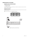
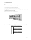
Table F identifies the terminal block pin assignments. On the terminal block, pin 1 is on the left (refer to Figure 18).
These pins, labels, and leads also correspond to alarms 5–8, 9–12, and 13–16 on the other three alarm terminal blocks.
To prevent false alarms on unused alarm inputs, leave the alarm in the Unsupervised mode with the Silent Alarm enabled (refer to Alarms Setup
on page 54 for a description of configuring and working with alarms).
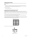
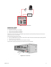
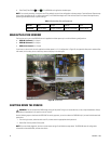
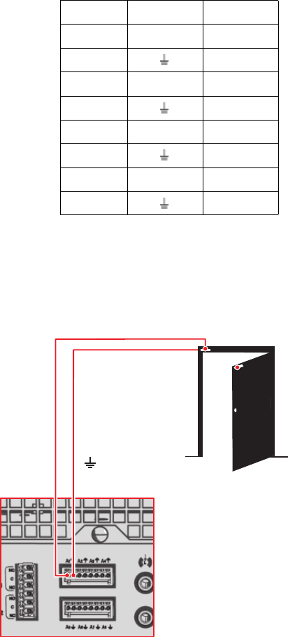
Figure 19 illustrates how to wire an alarm device to the Alarm 1 (A1) input. Refer to Table F for the specific connector pin assignments.
Figure 19. Connecting Alarms
CONNECTING A SEQUENCE MONITOR
Connect a composite video monitor to the SEQ output connector to display video from the analog cameras.
CONNECTING POWER
The internal DVR5100 autoranging power supply adapts automatically to voltages between 100 VAC and 240 VAC (50/60 Hz).
Use an uninterruptible power supply (UPS) (not supplied) for greater reliability. UPS devices maintain a limited amount of backup battery power in
case the main power fails. The UPS should have a minimum rating of 60 VA for 115 VAC, or 75 VA for 230 VAC.
To connect power:
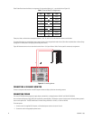
1. Connect one of the supplied US, European, or UK standard power cords to the rear of the unit.
2. Connect the cord to the appropriate power source.
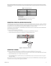
Table F. Terminal Block Pin Assignments
Pin Label Lead
1A1Alarm 1
2Ground
3A2Alarm 2
4Ground
5A3Alarm 3
6Ground
7A4Alarm 4
8Ground
A1


