VG4 Modular Camera System Getting Started | en 7
Bosch Security Systems, Inc. User’s Manual F.01U.133.268 | 6.0 | 2010.03
1 Getting Started
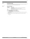
Install and wire the AutoDome according to the Bosch AutoDome Modular Camera System
Installation Manual. A typical system includes a keyboard, matrix switcher, monitor, and
appropriate wiring connections. Please refer to the individual product manuals for complete
installation and setup instructions for each of the system components.
1.1 Powering On
When you turn the AutoDome power on there is a ten (10) second pause before the dome
starts its homing phase. During the homing phase the camera pans left and right and tilts up
and down. It also adjusts the lens focus. The entire homing phase lasts approximately 40
seconds and ends with a splash screen.
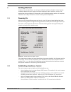
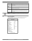
Figure 1.1 Sample VG4 Startup Splash Screen
The splash screen displays the type of AutoDome, the camera installed, the firmware levels for
various files, and the current IP address (if the AutoDome contains the IP Communications
module). The (P) to the right of the AutoDome series indicates that the AutoDome contains
the optional modules for maintaining internal pressure.
1.2 Establishing AutoDome Control
The most common ways to interface with the AutoDome are:
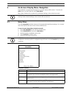
– Using a keyboard and on-screen display (OSD) menus. This method is the most common
and is covered in this manual.
– Using the AutoDome Configuration Tool software running on a PC with Bilinx or the RS-
232/485 communication protocol. Refer to the CTFID User Manual for instructions.
– Using a PC-based graphical user interface (GUI) such as the Bosch DiBos 8 software.
Refer to the DiBos 8 User Guide for instructions.
– Using the Bosch IP Web interface included with the IP Communications Module.
Bosch Security Sys. AutoDome(r)
500 Series(P)
Day/Night 26X
SC Boot
FPGA
Lang. Table
VCA_boot
IP-Panel
IP Address
Subnet Mask
No Heater
FastAddress: Not Set
1.10.00.02/1.07.58.02
2.00.00.00
1.05.00.01
1.13.01.05
1.00.00.01
1.02.00.01
4.10.50.13
10. 25.118.111
255.255.248. 0


