


xiii
Figures
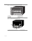
1-1 Matrix X4-C Chassis with Redundant Power Supplies....................................................................... 1-2
1-2 Matrix X4-C Chassis as Shipped (Rear View).................................................................................... 1-2
3-1 Disassembly Steps 1 and 2 ................................................................................................................ 3-2
3-2 Disassembly Steps 3 and 4 ................................................................................................................ 3-3
3-3 Disassembly Steps 5 through 8.......................................................................................................... 3-3
3-4 Installing Rack Support Brackets........................................................................................................ 3-6
3-5 Fastening Mid-Mount Brackets........................................................................................................... 3-7
3-6 Rack Mounting the Matrix X4-C Chassis............................................................................................ 3-8
3-7 Rack Mounting the Mid-Mounted Chassis.......................................................................................... 3-9
3-8 Telcordia GR-1089 Grounding Hole Pattern and Cable ................................................................... 3-10
3-9 ESD Grounding Receptacle ............................................................................................................. 3-11
3-10 Power Supply Planning: N + 1 Method............................................................................................. 3-12
3-11 Power Supply Planning: 1 + 1 Method ............................................................................................. 3-12
3-12 Removing Power Supply Vent Plate................................................................................................. 3-13
3-13 Installing Power Supply Module ....................................................................................................... 3-14
3-14 Removing Coverplate from Power Supply Slot ................................................................................ 3-14
3-15 Removing the AC Inlet Power Cord.................................................................................................. 3-15
3-16 Removing Fan Tray Bezel ................................................................................................................ 3-16
3-17 Installing Fan Tray ............................................................................................................................ 3-17
3-18 Installing IOMs.................................................................................................................................. 3-19
3-19 Engaging Ejector Handles ................................................................................................................ 3-19
3-20 Removing IOM Coverplate ............................................................................................................... 3-20
3-21 Installing Control Module .................................................................................................................. 3-21
3-22 Installing Fabric Module.................................................................................................................... 3-23
3-23 Installing XFP/SFP Optical Transceiver ........................................................................................... 3-25
3-24 Attaching LC or MT-RJ Cable Connector ......................................................................................... 3-26
3-25 Connecting an IBM PC or Compatible.............................................................................................. 3-28
3-26 Connecting a VT Series Terminal..................................................................................................... 3-29
3-27 Connecting to a Modem ................................................................................................................... 3-30
3-28 Attaching a USB Device to the CM................................................................................................... 3-32
3-29 Installing Flash Card......................................................................................................................... 3-32
3-30 Locating the DIMMs on the CM ........................................................................................................ 3-33
3-31 Removing the Existing DIMM ........................................................................................................... 3-34
3-32 Installing the Cable Management Assembly ....................................................................................3-36
3-33 Securing Cables Using the Velcro Cable Straps .............................................................................. 3-36
3-34 Connecting 20 Amp AC Power Cord to the Power Supply............................................................... 3-37
3-35 Power Supply LEDs.......................................................................................................................... 3-38
3-36 Fan Tray LED ................................................................................................................................... 3-39
3-37 Cable Management Base Panel LEDs ............................................................................................. 3-39
3-38 Fabric and Control Module LEDs and Reset Button......................................................................... 3-4
0
A-1 COM Port Pin Assignments................................................................................................................A-8