


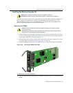
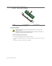

Attaching Cables, Installing Compact Flash Card and DIMM Upgrade Kit
Matrix X4-C Chassis Installation Guide 3-27
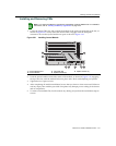
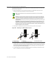
5. Afterthechassishasbeenpoweredup,verifyalinkexistsbycheckingthattheportRXLEDis
on(flashingamber,blinkinggreen,orsolidgreen).IftheRXLEDisoff,performthefollowing
stepsuntilitison:
a. Verifythedeviceattheotherendofthesegment
isonandlinkedtothesegment.
b. Ifthereareseparatefiber‐opticconnectionsontheotherdevice,checkthecrossoverofthe
cables.Swapcableconnectionsifnecessary.
c. Checkthatthefiber‐opticconnectionmeetsprescribeddBlossandcablespecifications.
6. Repeatsteps1through3,above,untilallconnectionshave
beenmade.
7. ToremovetheLCorMT‐RJcableconnector,pressitsreleasetabandpullitoutofthe
transceiver.
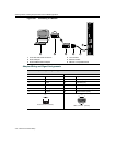
Connecting to the CM COM Port
ThissectiondescribeshowtoinstallaUTPcablewithRJ45connectorsandoptionaladaptersto
connecttheCMCOMporttoaPC,VTseriesterminal,ormodemtoaccesslocalmanagement.
Thissectionalsodetailsadapterpinoutassignments.
Thefollowingpartsmaybeneeded,dependingontheconnection:
•RJ45‐to
‐DB9femaleadapter(user‐supplied)
•UTPcablewithRJ45connectors(user‐supplied)
•RJ45‐to‐DB25femaleadapter(user‐supplied)
•RJ45‐to‐DB25maleadapter(user‐supplied)
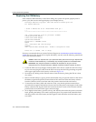
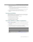
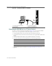
Connecting the CM COM Port to an IBM PC or Compatible Device
ToconnectanIBMPCorcompatibledevice,runningtheVTterminalemulation,totheCMCOM
port(Figure 3‐25),proceedasfollows:
1. ConnecttheRJ45connectoratoneendofthecabletothecommunicationsCOM(Console)
portontheCM.
2. PlugtheRJ45connectorattheotherendof
thecableintoauser‐suppliedRJ45‐to‐DB9adapter.
3. ConnecttheRJ45‐to‐DB9adaptertothecommunicationsportontheIBMPC.
4. TurnonthePCandconfigureyourVT emulationpackagewiththeseparameters:
5. ConnecttheX4‐C’spowercords.Referto“PoweringUptheMatrixX4‐C
Chassis”on
page 3‐37.
Parameter Setting
Mode 7 Bit Control
Transmit Transmit=19,200
Bits Parity 8 Bits, No Parity
Stop Bit 1 Stop Bit