


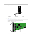
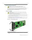
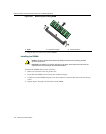

Attaching Cables, Installing Compact Flash Card and DIMM Upgrade Kit
3-30 Matrix X4-C Chassis Setup
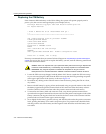
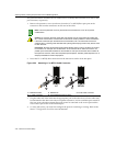
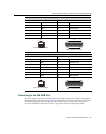
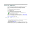
Figure 3-27 Connecting to a Modem
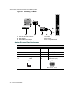
Adapter Wiring and Signal Assignments
1 UTP cable with RJ45 connectors 4 Local modem
2 RJ45 COM port 5 Remote modem
3 RJ45-to-DB25 modem adapter 6 IBM PC or compatible device
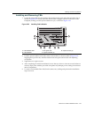
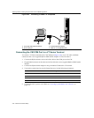
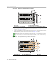
STATUS
ACTIVE/
STANDBY
RESET
USB
ETHERNET
COM
2
5 34 16
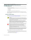
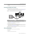
COM Port Adapter Wiring and Signal Diagram
RJ45 DB9
Pin Conductor Pin Signal
1 Blue 2 Receive (RX)
4 Red 3 Transmit (TX)
5 Green 5 Ground (GRD)
2 Orange 7 Request to Send (RTS)
6 Yellow 8 Clear to Send (CTS)
RJ45 Connector (Female)
81
Pins
DB9 Connector (Female)
Pins
15
69