


Matrix X4-C Chassis Installation Guide 1-1
1
Overview
Thischapterdescribesthefollowing:
System Description
TheMatrixX4‐CchassisdesignprovideseightslotstoseatfourInput/OutputModules(IOM),
twoFabricModules(FM),andtwoControlModules(CM).
TheMatrixX4‐Cchassissupports:
•Terabitswitchingcapacity
•Hotswappingofmodules
•Redundantpowerandcoolingsystems
• Installationinastandard19‐inch(48.26‐centimeter)widerack(six
chassiscanbeloadedintoa
standard7‐foot[213.36‐centimeter]highrack)
•ProtectiveearthgroundingrequirementsoftheNationalElectricalCode(NEC)UL60950and
IEC 60950standards
•TelcordiaGR‐1089Section9,BondingandGroundingRequirements,whenrequired
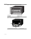
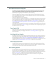
Allchassiscomponents(powersupplies,fantray,andmodules)areinstalledfromthe
frontofthe
chassisforeaseofmaintenance.AllLEDindicatorsareobservablefromthefrontofthechassisto
aidinmonitoringnetworkoperationalstatusandperformingmaintenance.Figure 1‐1illustrates
theMatrixX4‐Cchassis(frontview)asshippedfromthefactorywithcoverplatesremovedfrom
allslotslabeled
1includingCM1,FM1,PS1,thefirstIOMandfantrayslots.Figure 1‐2illustrates
therearofthechassisshowingACpowerinlets1through3andearthgroundingholes.
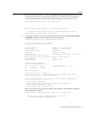
For information about: Refer to page ...
System Description 1-1
Features 1-3