


Setting Up the Matrix X4-C Chassis
3-10 Matrix X4-C Chassis Setup
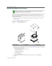
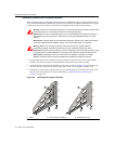
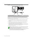
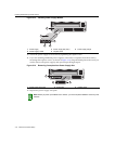
Figure 3-8 Telcordia GR-1089 Grounding Hole Pattern and Cable
TogroundthechassisaccordingtotheTelcordiaGR‐1089Section9,BondingandGrounding
Requirements,aconnectionisneededbetweenthechassisandtheenclosuremetalworkora
nearbypointontheCentralOffice(CO)Groundsystem.Theconnectionismadeusingoneor
moregroundingwires(asneeded)
fabricatedfroma12AWGstrandedcopperwire.Tofa bricate
andinstallagroundingwire,proceedasfollows:
1. Cuta12AWGstranded‐copperwiretolength,longenoughtoreachfromthegrounding
locationofthechassistotheselectedgroundinglocationontheCOGroundorenclosure
metalwork.
2. Install
alistedtwo‐holecompression‐typeconnectoronbothendsofthegroundingwire.
3. Applyasuitableantioxidanttothechassisgroundinglocationandunpaintedsurface
groundinglocationontheCOGroundorenclosuremetalwork.
4. Connectonegroundcabletwo‐holeconnectortothechassisusingtwoofthe1/4‐20screws
shippedwiththechassis.Connectthetwo‐holeconnectorattheotherendofthecabletothe
COGroundorenclosuremetalworkusinguser‐suppliedscrews.
5. Torquescrewsto67in‐lbs(±5%).
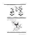
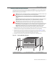
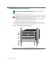
1 12 AWG stranded copper wire 3 Chassis 5 1/4-20 ground screws (4)
2 Rear of chassis, bolt pattern grounding site 4 Two-hole connectors
Notes: The hole pattern in the chassis allows you to use two differently-sized two-hole connectors,
determined by the orientation of the connector. Vertical and horizontal orientations allow for two
standard double-hole compression ground lug configurations.
In Norway, Sweden, and Finland, the same procedure can be used for a permanent protective earth
ground connection as required by their national deviation from IEC 60950, Section 5.1.7.
In Denmark, the chassis must be installed utilizing a Type B grounded plug.
14 4
3
2
2
5