


Installing and Removing a Power Supply
Matrix X4-C Chassis Installation Guide 3-15
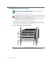
Removing a Power Supply
Toremoveapowersupply,proceedasfollows:
1. Attachtheanti‐staticwriststrapasdescribedin“AttachingtheElectrostaticDischargeWrist
Strap”onpage 3 ‐11beforehandlingthepowersupplymodule.
2. Unplugtheassociatedpowercordfromthe20A/100‐125Vac(or8A/200‐240Vac)outlet.
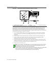
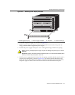
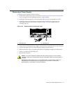
3. Unplugthepowercordfrom
theACinlet(associatedwiththepowersupplyyouare
removing)atthebackofthechassis,asshowninFigure 3‐15.Forexample,inletAC1
correlateswithPS1.
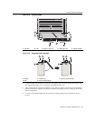
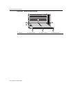
Figure 3-15 Removing the AC Inlet Power Cord
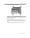
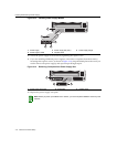
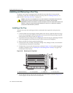
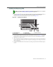
4. Loosenscrewssecuringthepowersupplyventplatetothechassisandremovetheventplate.
5. Unscrewthecaptivescrewto
releasethepowersupplyfromthechassis.
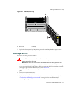
6. Removethepowersupplybygraspingthehandleandpullingitstraightoutofthechassis.
7. Fastenacoverplateovertheemptyslot.
8. Reinstalltheventplate.
1 Inlet power cord 2 AC inlet (AC1)
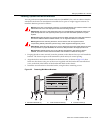
Caution: If you plan to operate the chassis with only one power supply, be sure to install the
coverplate in place of the removed power supply to contain EMI radiation and ensure proper air
circulation.
Precaución: Si desea trabajar sólo con una fuente de poder, no olvide colocar la tapa en el
compartimiento de la fuente de poder que haya eliminado, para reducir la interferencia
electromagnética y para asegurar una buena ventilación.
1
2
AC INLET 3
100 - 125V ~ 15A
200 - 240V ~ 8A
50/60 Hz
AC INLET 2
100 - 125V ~ 15A
200 - 240V ~ 8A
50/60 Hz
AC INLET 1
100 - 125V ~ 15A
200 - 240V ~ 8A
50/60 Hz
CAUTION: THIS UNIT MAY HAVE MORE THAN ONE
POWER SUPPLY CORD. DISCONNECT THREE (3)
POWER SUPPLY CORDS BEFORE SERVICING TO
AVOID ELECTRIC SHOCK.
VORSICHT: DIESES GERÄT HAT MEHR ALS EINEN
NETZANSSCHLUß. TRENNEN SIE VOR
WARTUNGSARBEITEN DIE 3 NETZANSCHLÜSSE VOM
NETZ, UM ELEKTRISCHE SCHLÄGE ZU VERMEIDEN.