


Installing and Removing Modules
Matrix X4-C Chassis Installation Guide 3-21
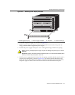
Installing and Removing CMs
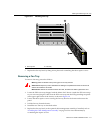
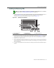
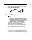
1. LocatetheemptyCM1slot,andpositionthemoduleintheguiderailattheleftoftheslot,as
showninFigure 3‐21.Gentlyinsertthemoduleuntilitengageswiththebackplane
connectors.BesuretheejectorhandlesareopenasshowninFigure 3‐19.
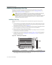
Figure 3-21 Installing Control Module
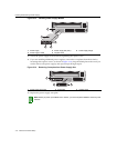
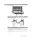
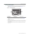
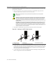
2. Pushtheejectorhandlestowardthecenterofthemodule,asshowninFigure 3 ‐19,engaging
thelipoftheslot,untilthemodulelocks intoplaceandisflushwithadjoiningcoverplates.
3. Tightenthetwocaptivescrews.
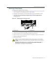
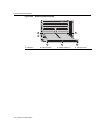
4. Aftercompletingallmoduleinstallation,besurethatyouleavenoslotsuncovered.Failureto
seal
anyemptyslotswiththe providedcoverplatesmayhamperpowercoolingofthechassis
anditscomponents.
5. Toremoveaninstall edCM,firstdisconnectanycablingandperformtheinstal lationstepsin
reverse.
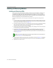
Note: If you ordered the Memory Upgrade Kit (X-4G-MEM), install the DIMMs first. For installation
instructions, refer to “Installing the Memory Upgrade Kit” on page 3-33.
1 Control Module slot 1 3 CM guide rails 5 Captive screws (2)
2 Control Module 4 Ejector handles (2)
FM2
FM1
STATUS
TX
RX
TX
RX
TX RX TXRX
X-M2-00
10G ENET
MAC ADD.
S/N:
S/N: MAC ADD.
GROUND
STRAP
2
1
CM2
CM1
4
3
2
1
FAN
TRAY
Matrix
X4
FAN
TRAY
STATUS
ACTIVE/
STANDBY
RESET
USB
ETHERNET
COM
3
5
3
1
5
2
4
4