


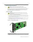
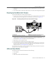
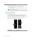


LEDs and Reset Button
Matrix X4-C Chassis Installation Guide 3-41
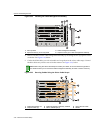
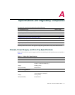
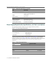
Table 3-3 Control and Fabric Module LED Definitions
Thefollowingadditionalconditionsapply:
•Aftermodulepowerup,theCM/FMSTATUSLEDwillremainreduntildiagnosticsbegin
thenwillblinkgreen.
•Aftermodulepowerup,theACTIVE/STANDBYLEDwillinitiallyindicateStandbystateuntil
itregisterseithertheActiveorStandbystate.
•Whenalinkisnotpresent,theSpeed
LEDwillbeoff.
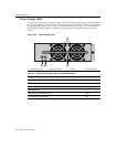
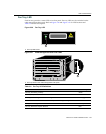
IOM LEDs
AllIOMcardsincludeoneStatusLEDforthecardandTransmitandReceiveorLink/Activityand
SpeedLEDsforeachport.RefertotheQuickReferencecardforyourIOMsformorespecificLED
information.
LEDdefinitionsfortheStatusLEDandtheTX/RXLEDsforsingle‐speedEthernetports
aregiven
inTable 3‐4.
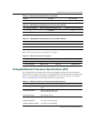
CM & FM LEDs State LED Activity
Status Not powered Off
Diagnostics failed, module requires attention, or state before
initialization is complete
Red
LED blinks during initialization and diagnostics Blinking green
Diagnostics passed and software operational Green
Both chassis PROMs failed Amber
Active/Standby Not powered Off
Power on but not configured, hardware not initialized Red
Module is Active Green
Module is on Standby Amber
CM LEDs Only State LED Activity
Ethernet Status
(Link)
Link established Green
Link established and traffic flowing Blinking green
Unpowered, link or system failure, or administratively disabled Off
Ethernet Speed
(10/100/1000)
1000 Mbps Off
100 Mbps Green
10 Mbps Yellow