


Installing and Removing Modules
Matrix X4-C Chassis Installation Guide 3-19
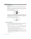
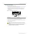
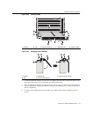
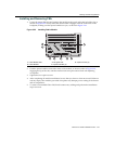
Figure 3-18 Installing IOMs
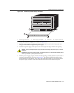
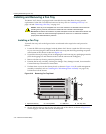
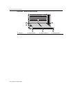
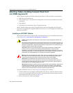
Figure 3-19 Engaging Ejector Handles
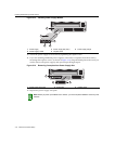
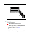
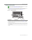
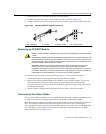
7. Toinstalladditionalmodules,removethecoverplatesfromtheslots,asshowninFigure 3‐20,
andrepeatearliersteps.Savecoverplatesforoptionalfutureuse.
8. Aftercompletingallmoduleinstallation,besurethatyouleavenoslotsuncovered.Failureto
sealanyemptyslotswiththeprovidedcoverplates,mayhamper
powercoolingofthechassis
anditscomponents.
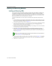
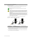
9. Toremoveaninstall edIOM,firstdisconnectanycablingandperforminstallationstepsin
reverse.
1 IOM slot 1 2 IOM 3 Captive screws (2) 4 IOM guide rails 5 Ejector handles
1 Module 3 Chassis rail 5 Ejector handle (closed)
2 Slot 4 Ejector handle (open)
FM2
FM1
S/N: MAC ADD.
GROUND
STRAP
CM2
CM1
4
3
2
1
FAN
TRAY
Matrix
X4
FAN
TRAY
STATUS
TX
RX
TX
RX
TX RX TX RX
X-M2-00
10G ENET
MAC ADD.
S/N:
2
1
3
3
4
4
55
1
2
3
5
1
2
3
4